Automobile wheel casing fender structure

A technology for fenders and automobile wheels, which is applied in the direction of upper structure, upper structure sub-assembly, vehicle parts, etc., can solve the problems of increased wheel rotation resistance, looseness and falling off, poor heat dissipation effect of wheels, etc., and achieves the goal of improving the heat dissipation effect Effect

Active Publication Date: 2013-01-02
ZHEJIANG GEELY AUTOMOBILE RES INST CO LTD +1
View PDF5 Cites 13 Cited by
  • Summary
  • Abstract
  • Description
  • Claims
  • Application Information

AI Technical Summary

Problems solved by technology

[0003] The purpose of the present invention is to overcome the poor heat dissipation effect of the wheels of existing automobiles, and the existing wheel radiators will not only increase the resistance of the wheels to rotate; Automotive wheel cover fender structure for heat dissipation effect of wheels and wheel brakes

Method used


Image

  • Automobile wheel casing fender structure
  • Automobile wheel casing fender structure
  • Automobile wheel casing fender structure

Examples


Embodiment 1

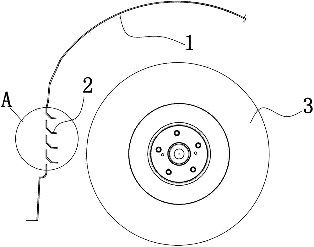
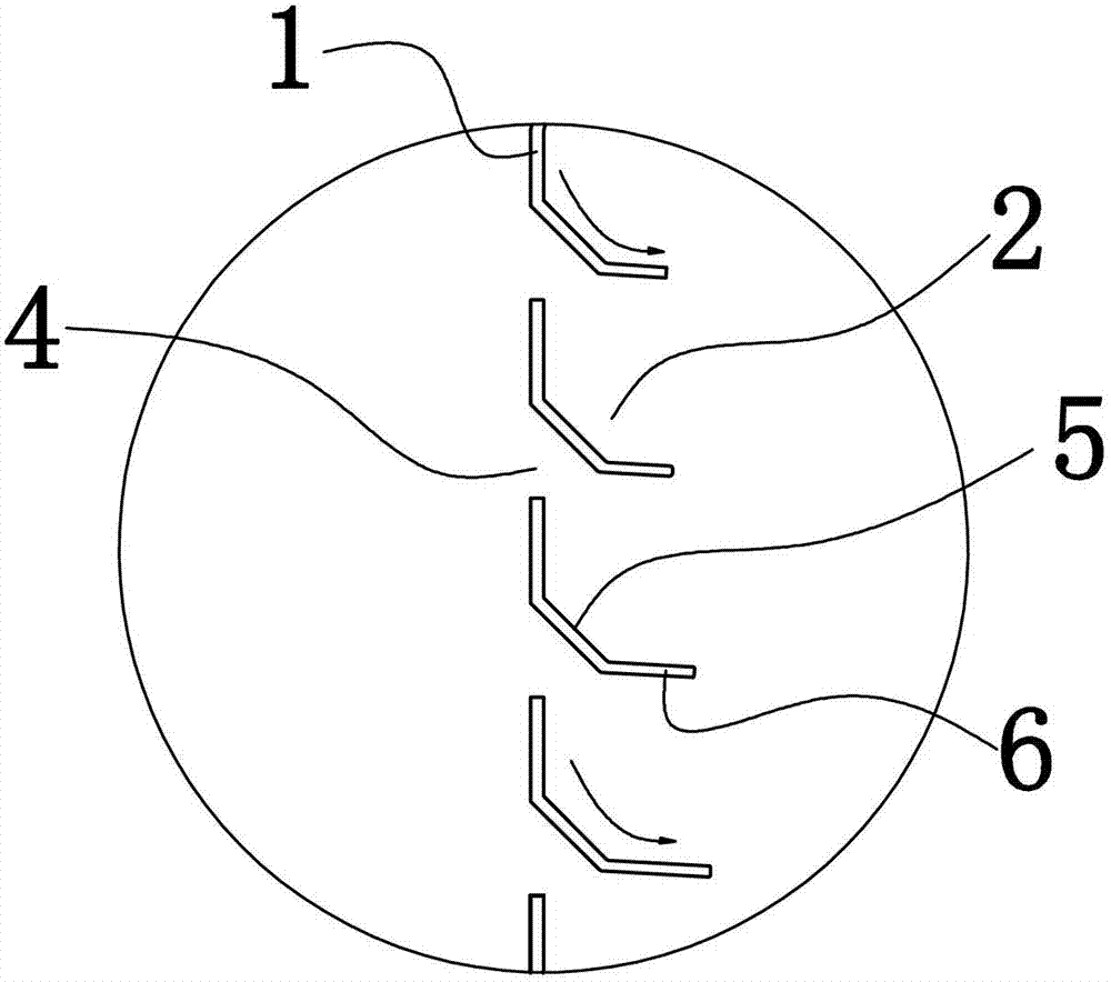
[0020] Embodiment 1: as figure 1 , figure 2 , image 3 As shown, a car wheel cover fender structure, the fender 1 is provided with a number of heat dissipation holes 4 on the front side of the wheel 3, and the upper edge of the heat dissipation holes is provided with a wind deflector 2 extending obliquely downward. The heat dissipation holes 4 are strip-shaped and extend from the outer side of the fender 1 to the inner side, and the heat dissipation holes 4 are evenly distributed from top to bottom. The wind deflector 2 also extends from the outer side of the fender to the inner side opposite to the cooling holes. Such as figure 2 As shown, the wind deflector 2 extends outward from the root of the wind deflector and includes an inclined portion 5 close to the root of the wind deflector and a guide portion 6 perpendicular to the fender. The length of each wind deflector 2 extending from the root to the outside gradually increases from top to bottom.

[0021] Since there ...

Embodiment 2

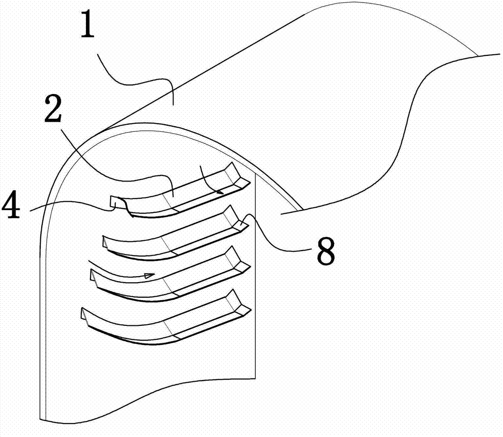
[0025] Embodiment 2: as figure 1 , figure 2 , Figure 4 As shown, the fender 1 is provided with a number of heat dissipation holes 4 on the front side of the wheel 3, and the upper edge of the heat dissipation holes is provided with a wind deflector extending obliquely downward. The cooling holes 4 are strip-shaped and extend horizontally from the outer side of the fender to the inner side, and the cooling holes are evenly distributed from top to bottom. The wind deflector 2 also extends horizontally from the outer side of the fender to the inner side opposite to the cooling holes. Such as figure 2 As shown, the wind deflector 2 extends outward from the root of the wind deflector and includes an inclined portion 5 close to the root of the wind deflector and a guide portion 6 perpendicular to the fender. The length of each wind deflector 2 extending from the root to the outside gradually increases from top to bottom.

[0026] Such as Figure 4 As shown, the side of the ...


PUM


Abstract

The invention discloses an automobile wheel casing fender structure, and aims to provide an automobile wheel casing fender structure which is capable of effectively improving the radiating effect of automobile wheels and wheel brakes. The structure comprises a plurality of radiating holes arranged on the fender on the front side of the wheels, wherein the radiating holes are strip-like and extend from the outer side to the inner side of the fender; the radiating holes are uniformly distributed from top to bottom; the upper edge of the radiating hole is provided with an air deflector extending in an inclined downward manner; and the air deflector extends from the root of the air deflector to the outside and comprises an inclining part close to the root of the air deflector and a guide part perpendicular to the fender.

Description

technical field [0001] The invention relates to an automobile wheel cover fender structure, in particular to an automobile wheel cover fender structure capable of improving the wheel heat dissipation effect. Background technique [0002] When the car is running at high speed, the temperature of the wheel will rise sharply; on the other hand, the temperature of the wheel brake will also rise sharply during the braking process of the car. In order to improve the heat dissipation effect of the wheel, the inventor has made a wheel radiator. Wheel radiators are generally divided into two categories: air-cooled and water-cooled. The main disadvantages of water-cooled radiators are the complex structure and the need to replenish water sources. The air-cooled radiator is mainly installed on the wheel by the blade, and the blade rotates with the wheel to generate wind to achieve the purpose of heat dissipation. In the current air-cooled radiator, the blades are generally fixed on ...

Claims


Application Information

Patent Timeline
Patent Type & Authority Applications(China)
IPC IPC(8): B62D25/16
Inventor 陈实戴开红毕连生韦兴民吴成明赵福全
Owner ZHEJIANG GEELY AUTOMOBILE RES INST CO LTD
Why Eureka
Try Eureka