Lifting device of aluminum electrolytic cell

A technology of aluminum electrolytic cells and lifting devices, which is applied in the field of lifting devices, can solve the problems of affecting production progress, time-consuming and laborious, and low frequency of crane use, and achieves the effects of low cost, convenient use, and overcoming production progress

Inactive Publication Date: 2013-01-02
SUZHOU TIANHUA NONFERROUS METAL PROD
View PDF0 Cites 0 Cited by
  • Summary
  • Abstract
  • Description
  • Claims
  • Application Information

AI Technical Summary

Problems solved by technology

[0002] As we all know, the main equipment of the modern aluminum industry is the aluminum electrolytic cell. During the production process, it uses direct current to enter the carbon anode through the column busbar and anode busbar on the side of the tank, and a chemical reaction occurs at the interface melt between the carbon anode and the cryolite electrolyte. , the aluminum oxide dissolved in the cryolite electrolyte melt is electrolyzed into liquid metal aluminum, deposited at the bottom of the electrolytic cell, and then flows through the carbon cathode below, and flows out from the long sides of the electrolytic cell along the same number of cathode steel rods Electrolyzer; since most of the current electrolyzers are 55KA, 60KA, 70KA, 80KA, 114KA, 125KA, 160KA, 186KA, 200KA, 230KA, 240KA, 280KA, 300KA, 320KA and 350KA, the weight ranges from a few tons to dozens of tons , each overhaul of the electrolytic cell needs to be transported from the electrolytic workshop to the production site of the maintenance company by trailer for repair. Since the electrolytic cell itself is heavy, a 10-70-ton crane must be used for each loading and unloading. Due to the use of the crane The frequency is very low, and it is not cost-effective to maintain a crane. Therefore, many aluminum processing enterprises use rented cranes. The cost of renting out the crane is also relatively high, and it is also necessary to arrange the use time, which is time-consuming and laborious. If it cannot be delivered in time, it will also affect the production progress.

Method used


Image

  • Lifting device of aluminum electrolytic cell
  • Lifting device of aluminum electrolytic cell
  • Lifting device of aluminum electrolytic cell

Examples


Embodiment Construction

[0013] The present invention is described below in conjunction with accompanying drawing.

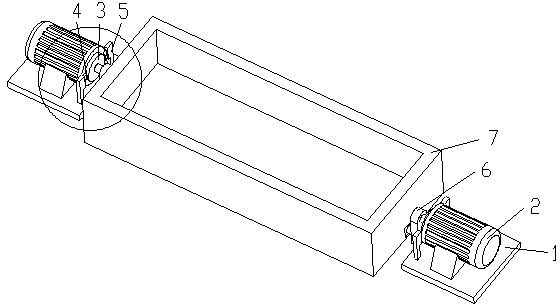
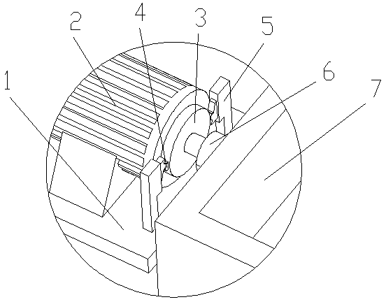
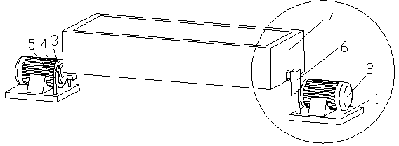
[0014] as attached Figure 1-4 The shown lifting device for an aluminum electrolytic cell according to the present invention includes a base 1, a motor 2, a turntable 3, a bump 4, an electromagnetic switch 5, a crank 6, and an aluminum electrolytic cell 7; the motor 2 is arranged on On the base 1; the output shaft of the motor 2 is provided with a turntable 3; the bump 4 is arranged on the outer circumference of the turntable 3; the electromagnetic switch 5 is provided with a group, which are respectively arranged on both sides of the turntable 3; The bump 4 can touch the electromagnetic switch 5 when the turntable 3 rotates; the output shaft of the motor 2 is connected with a crank 6;

[0015] Due to the application of the above-mentioned technical solution, the present invention has the following advantages compared with the prior art:

[0016] The lifting device of the aluminum ele...


PUM


Abstract

The invention discloses a lifting device of an aluminum electrolytic cell, which comprises a base, a motor disposed on the base, a turntable disposed on the output shaft of the motor, a projection disposed on the outer circumference of the turntable, a group of solenoid switches disposed on the two sides of the turntable, respectively, the projection coming into contact with the solenoid switches when the turntable turns, and a crank connected with the output shaft of the motor, the other end of the crank being connected with the bottom of the side face of the aluminum electrolytic cell. By shifting the solenoid switches through the projection disposed on the turntable, the forward and the backward rotations of the motor can be controlled, and as a result, the forward and the backward rotations of the crank are controlled, to achieve the purpose of lifting up and putting down the aluminum electrolytic cell. The invention has low service cost and convenient application, and solves the influence of crane problems on productive tempo at the same time.

Description

technical field [0001] The invention relates to a lifting device, in particular to a device for lifting an aluminum electrolytic cell when it is repaired and loaded, and belongs to the technical field of aluminum electrolytic cell auxiliary equipment. Background technique [0002] As we all know, the main equipment of the modern aluminum industry is the aluminum electrolytic cell. During the production process, it uses direct current to enter the carbon anode through the column busbar and anode busbar on the side of the tank, and a chemical reaction occurs at the interface melt between the carbon anode and the cryolite electrolyte. , the aluminum oxide dissolved in the cryolite electrolyte melt is electrolyzed into liquid metal aluminum, deposited at the bottom of the electrolytic cell, and then flows through the carbon cathode below, and flows out from the long sides of the electrolytic cell along the same number of cathode steel rods Electrolyzer; since most of the current...

Claims


Application Information

Patent Timeline
Patent Type & Authority Applications(China)
IPC IPC(8): C25C3/10
Inventor 黄东林喜桂
Owner SUZHOU TIANHUA NONFERROUS METAL PROD
Why Eureka
Try Eureka