Anti-falling PDC drill bit shackle device
A drill bit and device body technology, applied in the field of anti-drop PDC drill bit shackles, can solve the problems of slipping out and falling into the well, deforming the drill bit, etc., to achieve the effects of improving safety, durability and safety
- Summary
- Abstract
- Description
- Claims
- Application Information
AI Technical Summary
Problems solved by technology
Method used
Image
Examples
Embodiment 1
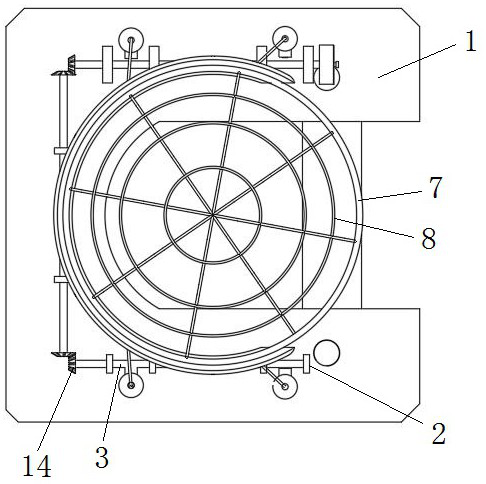
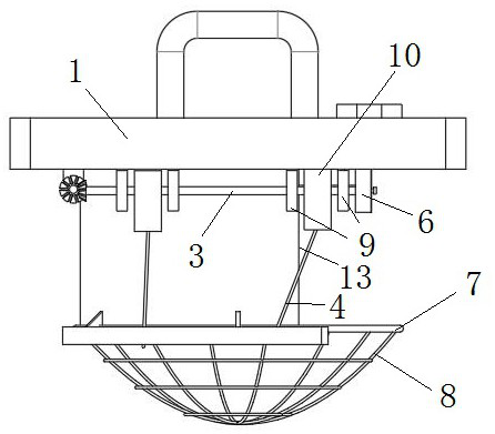
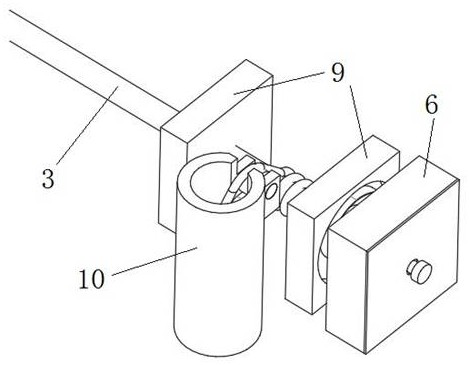
[0037] Such as Figure 1 to Figure 15 As shown, an anti-drop type PDC drill bit shackle includes a shackle body 1, a coil spring 5, a support frame 2 connected to the shackle body 1, and a support frame 2 connected to the shackle body 1. The accommodation frame 9, the power transmission shaft 3 connected to the support frame 2, the control module 6, the force application member 7, the net pocket 8, the power transmission shaft 3 is wound with a rope 4, and the power transmission shaft 3 The end of the rope 4 is connected to the control module 6, one end of the rope 4 is fixed on the force transmission shaft 3, the other end of the rope 4 is fixed on the force applying member 7, and the force applying element 7 is connected. The component 7 is connected with the net pocket 8, and the two ends of the curl spring 5 are respectively connected with the accommodation frame 9 and the power transmission shaft 3, and the power transmission shaft 3 can rotate.
[0038] The up and down ...
Embodiment 2
[0057] Such as Figure 1 to Figure 15 As shown, as a further optimization of Embodiment 1, this embodiment includes all the technical features of Embodiment 1. In addition, this embodiment also includes the following technical features:
[0058] In the present invention, the anti-drop type PDC drill bit shackle consists of a shackle body 1, a support frame 2, a force transmission shaft 3, a bevel gear 14, a coil spring 5, an accommodation frame 9, a bearing column 10, a control module 6, and a protection barrel 13. Composition of rope 4, ring (force applying part 7) and net bag 8, such as figure 1 shown. Wherein, the support frame 2 is connected with the shackle body 1 , and the support frame 2 has a shaft hole for supporting the rotation of the force transmission shaft 3 . A rope 4 and a coil spring 5 are wound between the two supporting frames 2 of the power transmission shaft 3 , and a square shaft section is provided at the right end for insertion into the control module...
PUM
 Abstract
Description
Claims
Application Information
 - R&D
- Intellectual Property
- Life Sciences
- Materials
- Tech Scout
- Unparalleled Data Quality
- Higher Quality Content
- 60% Fewer Hallucinations
Browse by: Latest US Patents, China's latest patents, Technical Efficacy Thesaurus, Application Domain, Technology Topic, Popular Technical Reports.
© 2025 PatSnap. All rights reserved.Legal|Privacy policy|Modern Slavery Act Transparency Statement|Sitemap|About US| Contact US: help@patsnap.com


