A Driving Mechanism Used on Cable Endurance Test Bench

A driving mechanism and durability test technology, which is applied to mechanical equipment, transmission devices, belts/chains/gears, etc., can solve the problems of affecting test results, cylinder damage, and increasing test costs, so as to achieve good test results, safe use, The effect of simple structure

Active Publication Date: 2015-09-30
金新民
View PDF7 Cites 0 Cited by
  • Summary
  • Abstract
  • Description
  • Claims
  • Application Information

AI Technical Summary

Problems solved by technology

[0002] At present, the driving mechanism used on the cable durability test bench usually drives the cable to reciprocate linear motion by the electric control cylinder. However, because the cable durability test needs to perform the above movement tens of thousands of times, the cylinder is prone to damage during this process. As a result, the test is terminated, which affects the test effect, and the use of a cylinder drive requires a complete set of electrical equipment, which undoubtedly increases the test cost

Method used


Image

  • A Driving Mechanism Used on Cable Endurance Test Bench

Examples


Embodiment Construction

[0013] The specific implementation manners of the present invention will be further described below in conjunction with the drawings and examples. The following examples are only used to illustrate the technical solution of the present invention more clearly, but not to limit the protection scope of the present invention.

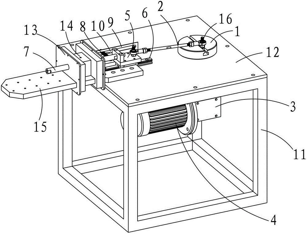
[0014] like figure 1 As shown, a driving mechanism used on a cable durability test bench includes a support frame, a turntable 1 that is rotatably connected to the support frame through a first rotating shaft, and a drive mechanism set on the turntable 1 for connecting The mounting hole at one end of the driving rod 2, the motor 3 and the reducer 4 that drive the first rotating shaft to rotate, the slider 5 that is fixedly connected to the other end of the driving rod 2, are arranged on the support The guide rail 6 on the frame, the cable installation frame fixedly connected with the slider 5, the transmission optical axis 7 arranged on the cable installat...


PUM


Abstract

The invention discloses a driving mechanism used on a dragline endurance test platform. The driving mechanism comprises a supporting frame, a turnplate which is connected with the supporting frame in a rotation manner through a first rotor shaft, a mounting hole which is formed in the turnplate and is used for connecting one end part of a drive rod, a motor and a speed reducer for driving the first rotor shaft to rotate, a sliding block fixedly connected with the other end part of the drive rod, a guide rail arranged on the supporting frame, a dragline mounting rack fixedly connected with the sliding block as well as a driving optical shaft arranged on the dragline mounting rack, wherein the mounting hole is deviated from the first rotor shaft, and the sliding block is arranged on the slide guide in a sliding manner; the sliding direction of the sliding block is perpendicular to an axial line direction of the first rotor shaft, the motor drives the turnplate to rotate, and then the drive rod is arranged in the mounting hole of the deviation rotating center; the drive rod can do reciprocating linear motion, and the drive rod drives the sliding block do reciprocating linear motion and further drives the dragline mounting rack to do reciprocating linear motion; therefore, the purpose of a test is achieved, the structure is simple, the use is safe, and a test effect is better.

Description

technical field [0001] The invention relates to a cable durability test bench, in particular to a driving mechanism used on the cable durability test bench. Background technique [0002] At present, the driving mechanism used on the cable durability test bench usually drives the cable to reciprocate linear motion by the electric control cylinder. However, because the cable durability test needs to perform the above movement tens of thousands of times, the cylinder is prone to damage during this process. Thereby the test is terminated, which in turn affects the test effect, and the use of a cylinder drive requires a complete set of electrical equipment, which undoubtedly increases the test cost. Contents of the invention [0003] The purpose of the present invention is to overcome the defects existing in the prior art, and provide a driving mechanism for a cable durability test bench, which has simple structure, low manufacturing cost and good test effect. [0004] In orde...

Claims


Application Information

Patent Timeline
Patent Type & Authority Patents(China)
IPC IPC(8): F16H21/18
Inventor 金新民
Owner 金新民
Why Eureka
Try Eureka