Electrically operated valve device

An electric valve device, electric valve technology, applied in valve device, lift valve, valve details and other directions, can solve the problems of high refrigerant, affect the performance of electric valve, etc., to achieve the effect of improving sealing

Active Publication Date: 2013-01-02
ZHEJIANG SANHUA INTELLIGENT CONTROLS CO LTD
View PDF4 Cites 13 Cited by
  • Summary
  • Abstract
  • Description
  • Claims
  • Application Information

AI Technical Summary

Problems solved by technology

Since the valve seat 105 is a thin-walled part, the length of the weld between the valve seat 105 and the valve seat core 107 is short, so the refrigerant in the valve cavity has a high probability of leaking to the outside along the weld, which affects the performance of the electric valve.

Method used


Image

  • Electrically operated valve device
  • Electrically operated valve device
  • Electrically operated valve device

Examples


Embodiment Construction

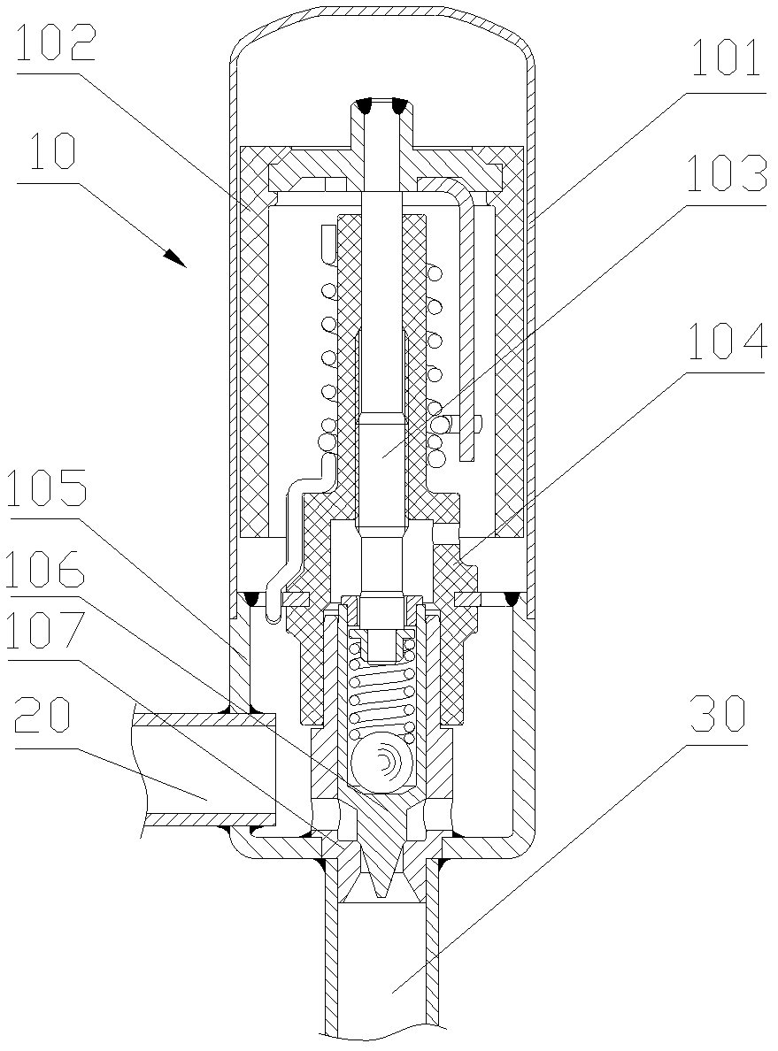
[0023] The core of the present invention is that the core of the present invention is to provide an electric valve device. In the electric valve device, the welding seam between the connecting pipe and the valve seat can block the refrigerant leaking from the welding seam between the valve seat and the valve seat core. Improve the sealing performance of the electric valve device.

[0024] In order to enable those skilled in the art to better understand the technical solutions of the present invention, the present invention will be further described in detail below in conjunction with the accompanying drawings and specific embodiments.

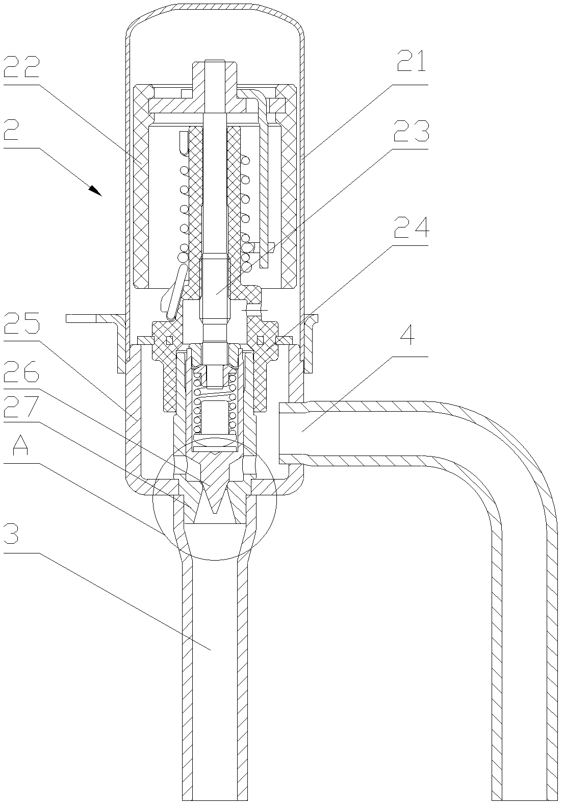
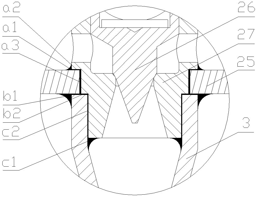
[0025] Please refer to figure 2 and image 3 , figure 2 It is a structural schematic diagram of the first specific embodiment of the electric valve device provided by the present invention; image 3 for figure 2 Partial enlarged schematic diagram of part A in the middle.

[0026] The electric valve 2 in the electric valve device include...


PUM


Abstract

The invention discloses an electrically operated valve device which comprises an electrically operated valve and a first connecting pipe connected with the electrically operated valve. The electrically operated valve is provided with a valve seat and a valve seat core. The valve seat core is plugged into an axial through hole of the valve seat to form a valve opening, the first connecting pipe is communicated with the valve opening, an outer peripheral wall of the valve seat core is welded and fixed with a peripheral wall of the axial through hole, and the upper end of the first connecting pipe and the bottom of the valve seat are welded and fixed. The upper end of the first connecting pipe of the electrically operated valve device is welded and fixed with the bottom of the valve seat, so that a formed weld joint can prevent a coolant permeated from a weld joint between the valve seat and the valve seat core from leaking, and the sealing performance of the electrically operated valve is improved.

Description

technical field [0001] The invention relates to the technical field of flow regulating valves, in particular to an electric valve device. Background technique [0002] In the refrigeration cycle system, an electric valve is usually set between the outdoor heat exchanger and the indoor heat exchanger. When in the cooling mode, the electric valve will throttle the refrigerant from the outdoor heat exchanger and direct it to the indoor heat exchanger; when in the heating mode, it will direct the refrigerant from the indoor heat exchanger to the outdoor heat exchanger after throttling and reducing the pressure . [0003] Please refer to figure 1 , figure 1 It is a structural schematic diagram of an electric valve device. [0004] The electric valve 10 has a casing 101 and a valve seat 105. The inside of the casing 101 is provided with a rotor device, a screw rod 103, and a nut 104. The upper end of the screw rod 103 is connected to the magnetic rotor 102 of the rotor device,...

Claims


Application Information

Patent Timeline
Patent Type & Authority Applications(China)
IPC IPC(8): F16K1/00F16K27/02F16K1/42
Inventor 不公告发明人
Owner ZHEJIANG SANHUA INTELLIGENT CONTROLS CO LTD
Why Eureka
Try Eureka