Display device and manufacturing method thereof

A technology for a display device and a manufacturing method, which is applied in optics, instruments, nonlinear optics, etc., can solve problems affecting display quality, uneven bonding pressure spacing, and increased production costs, so as to improve display quality and product yield, The thickness of the box remains uniform

Active Publication Date: 2013-01-02
BOE TECH GRP CO LTD
View PDF12 Cites 17 Cited by
  • Summary
  • Abstract
  • Description
  • Claims
  • Application Information

AI Technical Summary

Problems solved by technology

Since there is only an adhesive between the liquid crystal grating and the display panel after the box is assembled, there will often be a gap between the liquid crystal grating and the display panel caused by uneven bonding pressure, shrinkag

Method used


Image

  • Display device and manufacturing method thereof
  • Display device and manufacturing method thereof
  • Display device and manufacturing method thereof

Examples


Embodiment 1

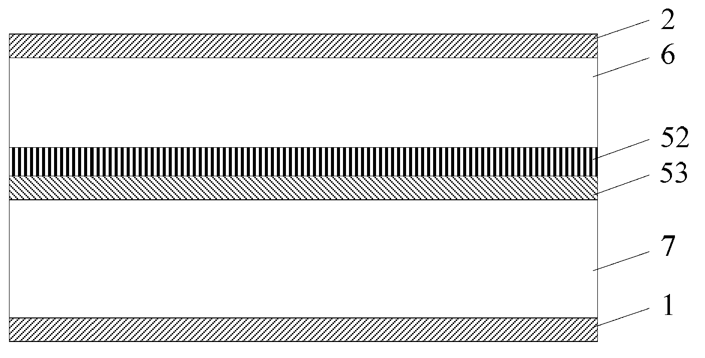
[0058] In the liquid crystal display device provided in Embodiment 1 of the present invention, the cell-thick support layer only includes one layer of support body, and the inter-cell polarizer can be installed on the upper surface of the substrate of the display panel and the lower surface of the lower substrate of the liquid crystal grating. The upper surface of the upper substrate of the selected display panel in the inter-cell polarizer can be arranged as the inter-cell polarizer, and the supporting body can form a surface including the lower surface of the lower substrate of the liquid crystal grating and the upper surface of the inter-cell polarizer (that is, non-bonding side of the polarizer in the box). Combine below figure 2 The structure of the liquid crystal display device provided by Embodiment 1 of the present invention will be described in detail.

[0059] like figure 2 As shown, the liquid crystal display device in this embodiment includes a first polarizer ...

Embodiment 2

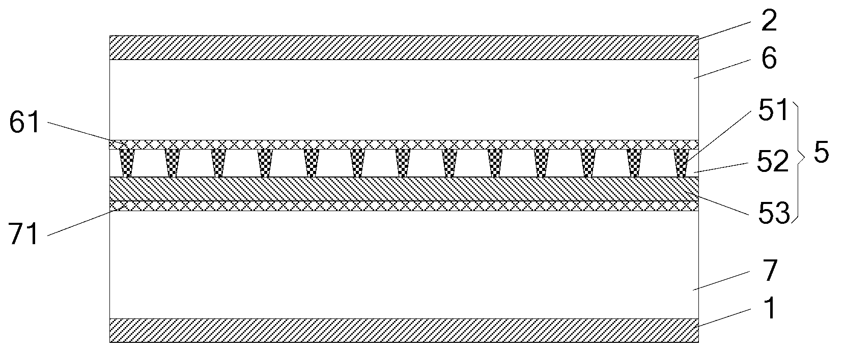
[0063] In the liquid crystal display device provided in Embodiment 2 of the present invention, the cell-thick support layer only includes one layer of support body, and the inter-cell polarizer can be arranged on the upper surface of the substrate of the display panel and the lower surface of the lower substrate of the liquid crystal grating. The setting surface of the polarizer is selected as the lower surface of the lower substrate of the liquid crystal grating, and the surface on which the support body can be formed includes the upper surface of the upper substrate of the display panel and the lower surface of the inter-cell polarizer. Combine below image 3 The structure of the liquid crystal display device provided by Embodiment 2 of the present invention will be described in detail.

[0064] like image 3 As shown, the liquid crystal display device provided by Embodiment 2 of the present invention also includes a first polarizer 1, a display panel 7, a cell thickness su...

Embodiment 3

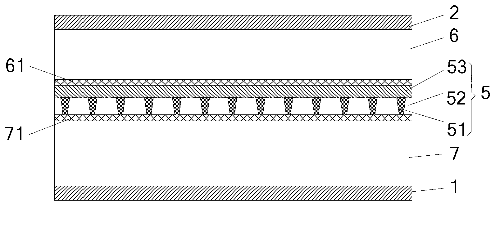
[0067]In the liquid crystal display device provided in Embodiment 3 of the present invention, the cell-thick support layer includes a layer of spacer substrate and two layers of support bodies, the support body located below the spacer substrate is called the first layer of support body, and the support body located above the spacer substrate It is called the second layer of support; the inter-cell polarizer can be arranged on the surface including the upper surface of the upper substrate of the display panel, the lower surface of the lower substrate of the liquid crystal grating, the lower surface and the upper surface of the spacer substrate; the inter-cell polarizer is selected as The upper surface of the upper substrate of the display panel; the surface on which the support can be formed includes the lower surface and the upper surface of the spacer substrate, the lower surface of the lower substrate of the liquid crystal grating, and the upper surface of the inter-cell pola...


PUM


Abstract

The invention provides a display device and a manufacturing method thereof. The display device comprises a display panel and a grating arranged on the light-emitting side of the display panel. The upper surface of the display panel and the lower surface of the grating are parallel to each other and are arranged adjacently. Box-thickness supporting layers are overlaid between the upper surface of the display panel and the lower surface of the grating and comprise at least one layer of support bodies. For each layer of support bodies, adhesion agents are filled in gaps between the support bodies, and the heights of the support bodies positioned at different positions are equal, so that the vertical distances from different position points on the upper surface of the display panel to the lower surface of the grating are equal. According to the display device and the manufacturing method of the display device, the space between the grating and the display device can be kept uniform, and accordingly the display quality of the display device and the product yield are improved.

Description

technical field [0001] The present invention relates to the field of display technology, in particular to a display device and a manufacturing method thereof. Background technique [0002] With the continuous development of display technology, people are no longer satisfied with flat display, so various stereoscopic display technologies emerge as the times require. Currently, stereoscopic display technologies are mainly classified into glasses-type 3D display technologies and naked-eye 3D display technologies (ie, unassisted stereoscopic display technologies). Among them, the glasses-type 3D display technology, as the name suggests, requires the audience to wear special glasses to watch the three-dimensional display effect. In practical applications, because the visual sensitivity of glasses-type 3D display technology is poor and does not conform to conventional viewing habits, people are turning more attention to naked-eye 3D display technology. [0003] The so-called nak...

Claims


Application Information

Patent Timeline
IPC IPC(8): G02B27/26G02F1/1335G02F1/1333G02B30/25
Inventor 李文波
Owner BOE TECH GRP CO LTD
Why Eureka
Try Eureka