
Light source system and projection device

A technology of a light source system and a reflective device, applied in the field of optics

Active Publication Date: 2013-01-02
APPOTRONICS CORP LTD
View PDF9 Cites 34 Cited by
  • Summary
  • Abstract
  • Description
  • Claims
  • Application Information

AI Technical Summary

Problems solved by technology

Light source used to generate excitation light

Method used


Image

  • Light source system and projection device
  • Light source system and projection device
  • Light source system and projection device

Examples


Embodiment Construction

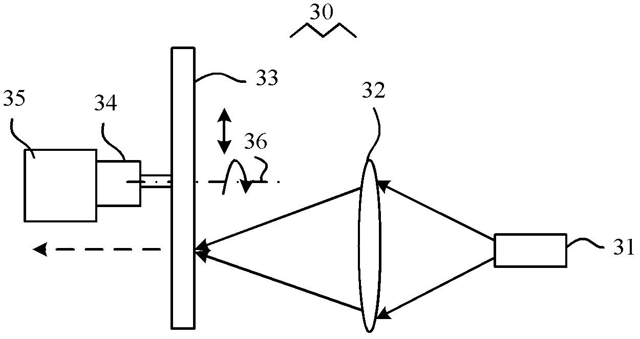
[0028] See image 3 , image 3 It is a structural schematic diagram of the first embodiment of the light source system of the present invention. Such as image 3 As shown, the light source system 30 of this embodiment mainly includes a light source 31 , a light collecting device 32 , a color wheel 33 , a driving device 34 and a switching device 35 .

[0029] In this embodiment, the excitation light generated by the light source 31 is collected and relayed by the light collecting device 32 and then incident on the color wheel 33 , and then received by the color wheel 33 . The driving device 34 periodically drives the color wheel 33 to rotate around the rotating shaft 36 . The switching device 35 moves the color wheel 33 and the driving device 34 in a direction perpendicular to the rotating shaft 36 .

[0030] See Figure 4 , Figure 4 yes image 3 The structure diagram of the first embodiment of the color wheel 33 is shown. Such as Figure 4 As shown, the color wheel 3...


PUM


Abstract

The invention provides a light source system and a projection device. A light source is used for generating an exciting light, a color wheel device is used for receiving the exciting light and comprises a first area and a second area, at least two first color sections are arranged on the first area, at least two second color sections are arranged on the second area, a driving device is used for periodically driving the color wheel device, so that under a first operating mode, the light source system can periodically output a first output light sequence formed by a first output light which is alternately generated by at least two first color sections arranged on the first area, under a second operating mode, the light source system can periodically output a second output light sequence formed by a second output light which is alternately generated by at least two second color sections arranged on the second area, the first output light sequence is different from the second output light sequence, and a switching device is used for controlling the light source system to be switched between the first operating mode and the second operating mode. According to the light source system and the projection device, at least two different output light sequences can be generated specific to different operating modes.

Description

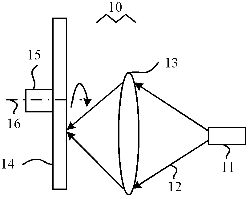
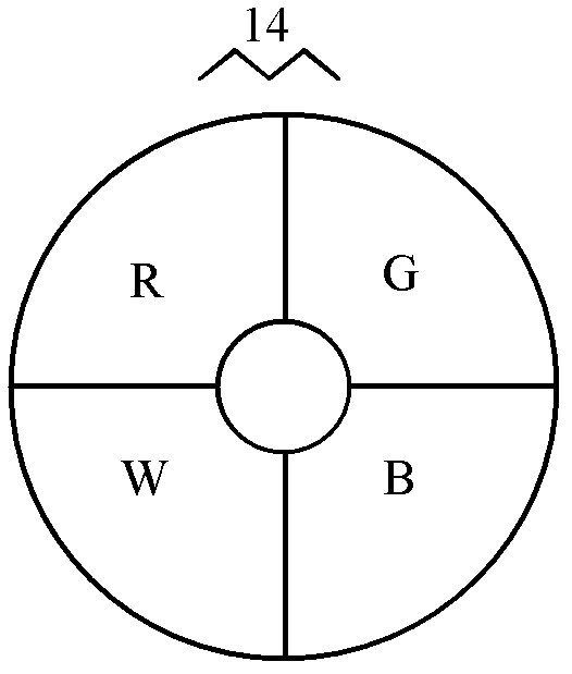
technical field [0001] The invention relates to the field of optical technology, in particular to a light source system and a projection device. Background technique [0002] Currently, colored light sequences are often used in the field of lighting and display. Such as figure 1 As shown, in a prior art light source system 10 , the excitation light 12 generated by the light source 11 is focused onto the color wheel 14 through the light collecting device 13 . The color wheel 14 includes a plurality of color segments, and different color segments are provided with different fluorescent materials, so that when the driving device 15 drives the color wheel 14 to rotate around the rotating shaft 16, the plurality of color segments of the color wheel 14 are alternately arranged in the excitation light 12 on the transmission path, and then excited by the excitation light 12 to generate a variety of colored light sequences. For example, if figure 2 As shown, the color wheel 14 i...

Claims


Application Information

Patent Timeline
Patent Type & Authority Applications(China)
IPC IPC(8): G03B21/20G03B21/14G03B21/00G02B7/00F21V14/08
CPCG03B21/00G03B21/20G03B21/204G03B21/28G03B33/06
Inventor 李屹曹亮亮杨毅
Owner APPOTRONICS CORP LTD
Learn More