
Optical module firmware in-application upgrading method capable of not interrupting service

一种应用升级、光模块的技术,应用在软件工程设计、仪器、电数字数据处理等方向,能够解决光模块损坏、消耗、中断业务等问题

Active Publication Date: 2013-01-02
WUHAN TELECOMM DEVICES
View PDF8 Cites 48 Cited by
  • Summary
  • Abstract
  • Description
  • Claims
  • Application Information

AI Technical Summary

Problems solved by technology

For example, if the online upgrade technology is not used in the existing optical module, the system manufacturer needs to adjust the performance index of the optical module, or the firmware of the optical module finds a design defect, the usual practice is that the optical module manufacturer recalls the module and uses a professional The download tool to re-download the firmware, which not only consumes a lot of manpower and transportation costs, but also easily causes damage to the optical module
At present, the control part of relatively high-end optical modules is mostly realized by MCU (Micro Control Unit, Micro Control Unit) based on ARM core. Upgrading technology currently has some obvious shortcomings in the application field of optical modules. The biggest problem is that the firmware update solutions provided by MCU manufacturers all require MCU to perform a reset operation before or after firmware upgrade without exception. Once it comes, the optical module in normal communication will interrupt the business, which will cause unpredictable risks to the operator
At the same time, the in-application upgrade technology provided by most MCU manufacturers uses serial ports or network interfaces to download and update firmware, which is also unacceptable for small optical modules.

Method used


Image

  • Optical module firmware in-application upgrading method capable of not interrupting service
  • Optical module firmware in-application upgrading method capable of not interrupting service
  • Optical module firmware in-application upgrading method capable of not interrupting service

Examples


Embodiment Construction

[0022] In order to facilitate a further understanding of the method of the present invention, preferred embodiments are described in detail below in conjunction with the accompanying drawings.

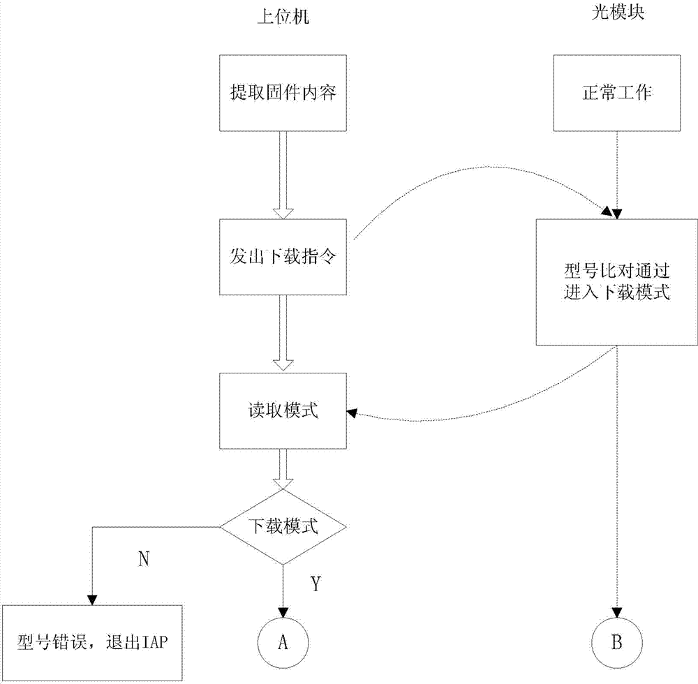
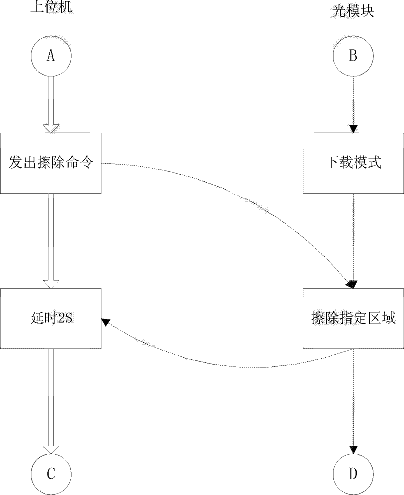
[0023] The present invention utilizes the characteristics of the MCU storage area, and divides two areas in the MCU internal program storage area to store the upgrade program and the application program respectively. For an MCU with 51 cores, the interrupt vector table of the Boot program is backed up by dividing a special area. For the MCU with ARM core, through the re-image operation, the interrupt vector table of the Boot program and the interrupt vector table of the application program are switched according to the needs, and the program jump is realized through the program pointer. Using the relocation technology of the interrupt vector table, the external command The way to control the MCU to switch freely between the two programs, and some registers, peripheral interfaces, I / O po...


PUM


Abstract

The invention discloses an optical module firmware in-application upgrading method capable of not interrupting service. Two areas are set in an optical module internal program storage area and are respectively used for storing an upgrade program and an application program, a special area is set and used for backing up an interrupt vector table of a Boot program, an upper computer communicates with an optical module, the interrupt vector table is switched, and the skip between the Boot program and the application program is realized through a program pointer. The method specifically comprises the following steps of: 1) extracting firmware contents; 2) entering a download mode and upgrading a firmware; 3) erasing the original firmware; 4) writing a new firmware; and 5) entering an application mode, wherein after data and codes are verified, the upper computer transmits a download mode exit command, the optical module firmware exits from the upgrade program and is switched to execute the new application program, and the optical module works normally. By adopting the optical module firmware in-application upgrading method capable of not interrupting service, since the switching between the application program and the upgrade program is controlled by the command which is transmitted by the upper computer and an MCU (micro control unit) is not required to be reset, the situation that the work of the optical module is interrupted is not caused.

Description

technical field [0001] The present invention relates to an in-application upgrade method, in particular to an in-application upgrade method for optical module firmware that can save labor costs and operating costs without interrupting services. Background technique [0002] As an important component in the current optical communication industry-optical modules, their production capacity is getting larger and larger, and their processes and control technologies are becoming more and more complex. With the diversification of business, optical communication system vendors have put forward higher requirements for optical module manufacturers. In this context, the firmware of the optical module is also paid special attention to by the system manufacturer in the application upgrade technology. For example, if the online upgrade technology is not used in the existing optical module, the system manufacturer needs to adjust the performance index of the optical module, or the firmwar...

Claims


Application Information

Patent Timeline
Patent Type & Authority Applications(China)
IPC IPC(8): G06F9/445
CPCG06F8/67G06F8/656
Inventor 袁涛余向红陈序光
Owner WUHAN TELECOMM DEVICES
Learn More