

Non-polarity safe charger circuit
A charger and non-polarity technology, which is applied to battery circuit devices, current collectors, circuit devices, etc., can solve the problems of fire, small number of batteries, and low safety factor, and achieve the effect of improving the safety factor
- Summary
- Abstract
- Description
- Claims
- Application Information
AI Technical Summary
Problems solved by technology
Method used
Image

Examples
Embodiment 1
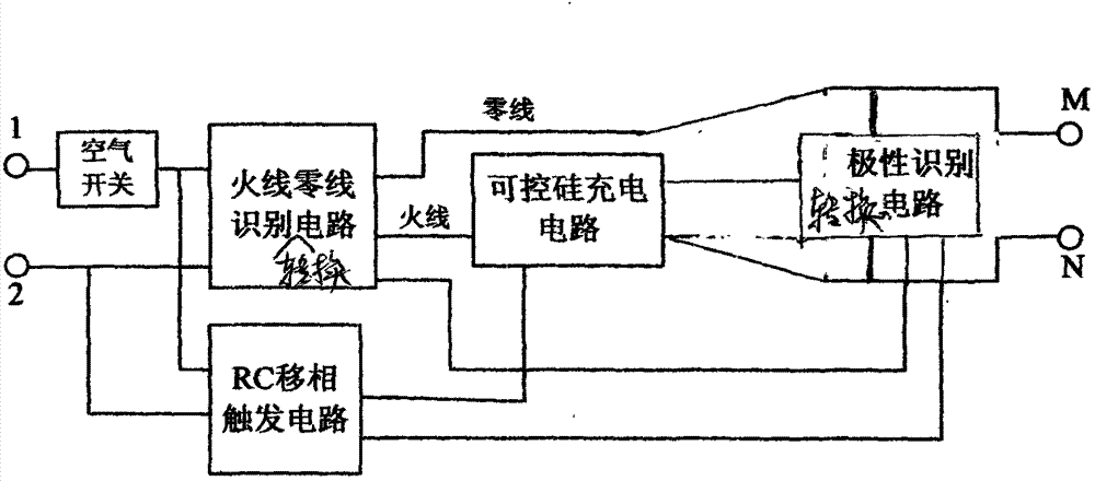
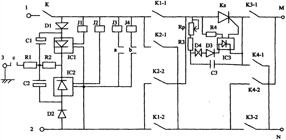
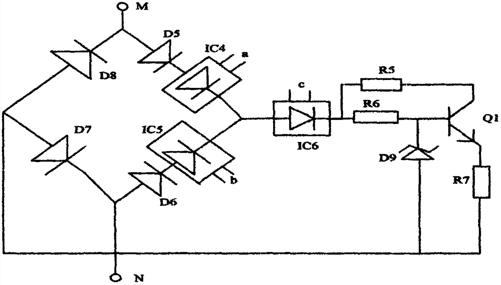
[0029] The non-polarity safety charger circuit of this embodiment, as figure 1 , which includes: live wire and neutral wire identification circuit, RC phase-shift trigger circuit, thyristor charging circuit and polarity identification circuit;
[0030] The input terminals of the live wire and neutral wire identification circuit and the RC phase-shift trigger circuit are respectively connected to the AC input terminal ( figure 1 The AC input terminal shown in the figure includes input terminal 1, input terminal 2) connection, the live wire output terminal of the live wire and neutral line identification circuit is connected to the input terminal of the polarity identification circuit through the thyristor charging circuit, and the neutral line of the live line and neutral line identification circuit The output terminal is connected to the input terminal of the polarity identification circuit, and the output terminal of the polarity identification circuit is connected to the pol...
Embodiment 2
[0077] The live wire and neutral wire identification circuit in Embodiment 1 can also be replaced by an isolation transformer, such as Figure 10 As shown, the non-polarity safety charger circuit in this embodiment includes: an isolation transformer, an RC phase shift trigger circuit, a thyristor charging circuit and a polarity identification circuit;
[0078] The primary coil of the transformer is connected to the input terminal of the mains, one end of the secondary coil of the transformer is connected to one end of the polarity output, the other end of the secondary coil of the transformer is connected to the other end of the polarity output through the thyristor charging circuit, and the polarity identification circuit is connected to the two ends of the polarity output. between the terminals; the output terminal of the polarity identification circuit is connected to the RC phase-shifting trigger circuit; the RC phase-shifting trigger circuit is connected to the control ter...
PUM
 Abstract
Description
Claims
Application Information