Bumper structure

一种保险杠、保险杠加强件的技术,应用在保险杠、车辆部件、车辆安全安排等方向,能够解决增加竖直重叠量、增加组装时间、增加部件数量等问题

Active Publication Date: 2013-01-02
TOYOTA JIDOSHA KK
View PDF8 Cites 4 Cited by
  • Summary
  • Abstract
  • Description
  • Claims
  • Application Information

AI Technical Summary

Problems solved by technology

[0004] However, the technique described in JP-A-2007-261525 is effective unless the bumper structures of the vehicles colliding with each other are exactly the same
In addition, the technique described in JP-A-2007-196827 requires the use of a separate member for the bumper reinforcement (bumper beam) to increase the amount of vertical overlap, so it has the disadvantages of increasing the number of parts, increasing assembly time, and increasing cost. shortcoming

Method used


Image

  • Bumper structure
  • Bumper structure
  • Bumper structure

Examples


no. 1 example

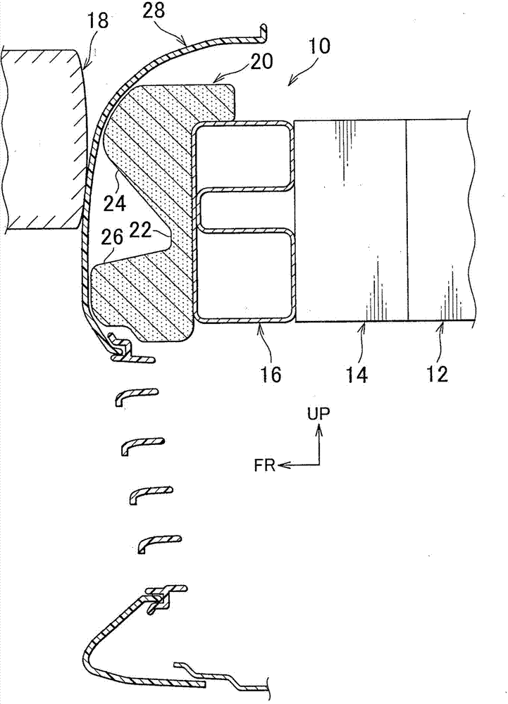
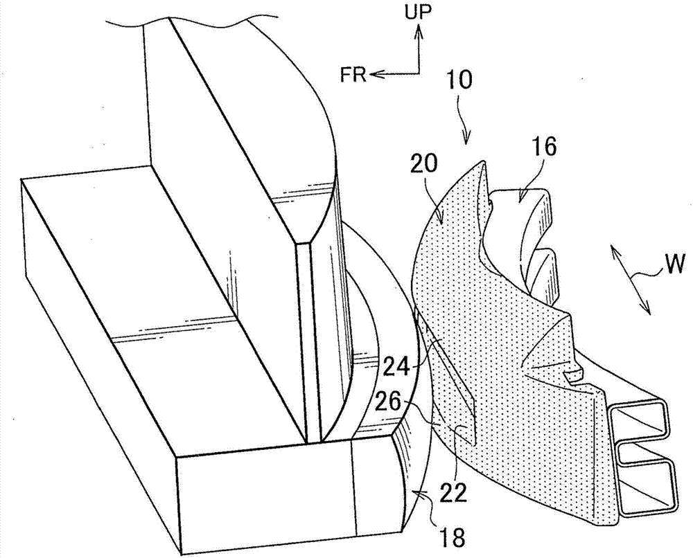
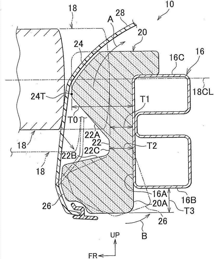
[0048] Next, a bumper structure according to a first embodiment of the present invention will be described with reference to the drawings. The first embodiment will be described based on an example in which a bumper structure of one aspect of the present invention is incorporated in a front bumper of a vehicle relatively small in height such as a racing car. Note that, in the drawings, an arrow "FR" indicates a direction toward the front side of the vehicle, an arrow "UP" indicates a direction toward the upper side of the vehicle, and an arrow "W" indicates a lateral direction of the vehicle.

[0049] like figure 1 As shown, the bumper structure 10 of the first embodiment includes a pair of front side members 12 provided at respective lateral sides of the vehicle and extending in the longitudinal direction of the vehicle, and a bumper reinforcement 16 extending in the lateral direction of the vehicle is attached. The crash box 14 is interposed between the bumper reinforcement...

no. 2 example

[0075] Next, we will refer to Figure 5 A bumper structure according to a second embodiment of the present invention is described. Note that the same elements as those in the first embodiment are denoted by the same reference numerals, and descriptions thereof will be omitted. The second embodiment is an example of incorporating a bumper structure of one aspect of the present invention in a rear bumper of a vehicle relatively small in height such as a racing car.

[0076] like Figure 5 As shown, in the bumper structure 10 of the second embodiment, reference numeral 128 denotes a rear bumper cover, and reference numeral 116 denotes a rear bumper reinforcement, and the bumper absorber 20 is attached to the rear bumper reinforcement 116 on the rear side of the vehicle.

[0077] The bumper structure 10 of the second embodiment applied to the rear bumper is basically the same as the bumper structure 10 of the first embodiment applied to the front bumper. The shape of the bumpe...

no. 3 example

[0081] Next, we will refer to Image 6 A bumper structure of a third embodiment of the present invention is described. Note that the same elements as those in the first embodiment are denoted by the same reference numerals, and descriptions thereof will be omitted. The third embodiment is an example of incorporating a bumper structure of one aspect of the present invention in a front bumper of a vehicle that is relatively high in height such as an RV.

[0082] like Image 6 As shown, the vertical height of the top surface 16C of the bumper reinforcement 16 relative to the vertical center height 18CL of the barrier 18 in the third embodiment is set higher than that in the first embodiment, measured from the road surface. The vertical height of the top surface 16C of the bumper reinforcement 16 relative to the vertical center height 18CL of the barrier 18. The upper portion of the bumper absorber 20 protrudes upward beyond the top surface 16C of the bumper reinforcement 16 (r...


PUM


Abstract

A recess (22) is formed at the center of a bumper absorber (20), provided on the vehicle outer side of a bumper reinforcement (16), so as to face forward, and an upper recess wall face (22A) of an upper absorber portion (24) located on the upper side of the recess (22) is inclined downward. If the subject vehicle is small in height and the amount of vertical overlap between the bumper absorber (20) and the rear bumper of other vehicle (a barrier (18) used in the narrow vertical overlap barrier test of the IIHS) is small, in the initial collision stage, the rear bumper of the other vehicle is guided by the inclined upper recess wall face (22A) to move relatively downward while the bumper of the subject vehicle moves relatively upward, preventing underride, increasing the amount of vertical overlap between the rear bumper of the other vehicle and the bumper absorber (20), and thus achieving reliable impact absorption.

Description

technical field [0001] The present invention relates to a vehicle bumper structure, and more particularly to a bumper structure having a bumper absorber for absorbing the impact of a collision with an object. Background technique [0002] Bumper absorbers (impact absorbing members) for absorbing impact at the time of collision are arranged on the vehicle longitudinal outer sides of the respective bumper reinforcements of the front and rear bumpers of the vehicle. Crash safety tests conducted by the Insurance Institute for Highway Safety (IIHS) in the United States include narrow vertical overlapping barrier tests. In this test, a curved barrier is used, the central portion of which is convex towards the outside in the longitudinal direction of the vehicle. The barrier was vertically deviated to partially overlap the bumper of the vehicle, and the front and rear sides of the vehicle collided with the barrier at 10 km / h. [0003] In a case where the vehicle height is relativ...

Claims


Application Information

Patent Timeline
Patent Type & Authority Applications(China)
IPC IPC(8): B60R19/18B60R19/22
CPCB60R19/18B60R2019/1873
Inventor 千叶健二末广仁嗣石岛崇弘中岛大辅
Owner TOYOTA JIDOSHA KK
Why Eureka
Try Eureka