Load supporting surface

A technique for supporting surfaces, supporting structures, applied in the direction of chairs, drawing tables, stools, etc.

Active Publication Date: 2013-01-09
ILLINOIS TOOL WORKS INC
View PDF7 Cites 4 Cited by
  • Summary
  • Abstract
  • Description
  • Claims
  • Application Information

AI Technical Summary

Problems solved by technology

Therefore, elastic fabrics may not be ideal in all applications

Method used


Image

  • Load supporting surface
  • Load supporting surface
  • Load supporting surface

Examples


Embodiment Construction

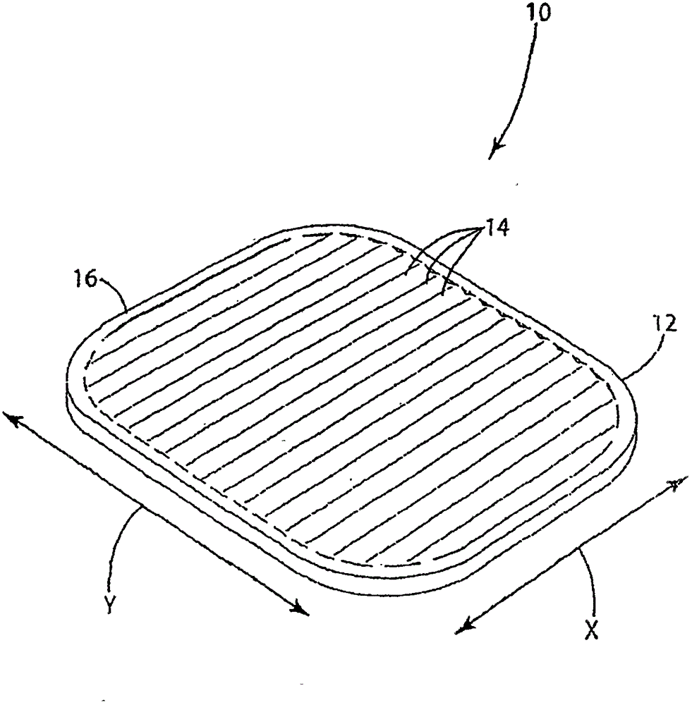
[0047] figure 1 A load bearing surface 10 according to one embodiment of the invention is shown in . figure 1 The load bearing surface 10 shown in is suspendable from a support structure such as a chair seat frame 100 ( Figure 18 with 19 shown) on the molded film. The load supporting surface 10 has different supporting properties in different directions. For example, a load bearing surface may provide significant elastic support in the x-direction and less support in the y-direction. This "divided" support characteristic of the load bearing surface provides a high level of comfort. By way of disclosure, the invention is described in connection with various alternative embodiments primarily for seating applications. However, the present invention is not limited to use in seating applications, but may also be incorporated into other load support applications. The support properties of the molded membrane are highly adjustable, making the load supporting surface 10 suitabl...


PUM


Abstract

The present invention relates to an elastic load supporting surface, which has different load supporting characteristics in different directions. In one embodiment, the surface comprises a directional elastic film along one direction through extrusion or drawing. In another embodiment, the surface comprises a mechanical structure, such as a connection portion and thickness deformation, and the structure changes the bearing characteristics of different directions. In another embodiment, the surface not only is directed, and but also comprises the mechanical structure.

Description

[0001] This application is a divisional application of the invention patent application with the application number 200680054523.8 and the application date of August 25, 2006, entitled "Load Support Surface". Background technique [0002] The parent application of this application is a continuation-in-part of U.S. Patent Application No. 11 / 112,345, filed April 22, 2005 (now U.S. Patent No. _), claiming U.S. Provisional Patent No. 60 / 580,648, filed April 22, 2005 Application priority. [0003] The present invention relates to a load supporting surface, in particular to a resilient load supporting surface, such as the seat or back of a chair or bench, or the supporting surface of a bed, cradle or other similar product. [0004] Efforts continue to develop new and improved load bearing surfaces. As for load bearing surfaces in general, the main purpose of these efforts is to obtain a durable and inexpensive load bearing surface. For backrests and other body support applications...

Claims


Application Information

Patent Timeline
IPC IPC(8): A47C5/12A47C7/14A47C7/74A47C7/28
CPCA47B27/14A47C5/12
Inventor 蒂莫西·P.·科菲尔德丹尼尔·S.·佐默费尔德安德鲁·B.·哈特曼
Owner ILLINOIS TOOL WORKS INC
Why Eureka
Try Eureka