Multifunctional safety and convenience conveying and rescuing groove
What is Al technical title?
Al technical title is built by PatSnap Al team. It summarizes the technical point description of the patent document.
A multi-functional and safe technology, applied in the field of transportation and rescue tanks, can solve the problems of shortage and lag of disaster relief facilities, and achieve the effects of convenient transportation and rescue, low manufacturing cost, and fast transportation and rescue.
Active Publication Date: 2015-05-13
LIUZHOU JINGYANG ENERGY SAVING TECH RES DEV
View PDF4 Cites 0 Cited by
Summary
Abstract
Description
Claims
Application Information
AI Technical Summary
This helps you quickly interpret patents by identifying the three key elements:
Problems solved by technology
Method used
Benefits of technology
Problems solved by technology
[0003] The purpose of the present invention is to solve the practical problems of shortage of existing disaster relief facilities and technological lag, and to provide a multi-functional disaster relief system with exquisite design, superior technical performance, wide multi-function and practicality, convenient transportation and rescue, high efficiency, safety and durability, and extremely low production cost. Safe and quick rescue chute
Method used
Image
Click on the blue label to locate the original text in one second.
Reading with bidirectional positioning of images and text.
Examples
Embodiment Construction
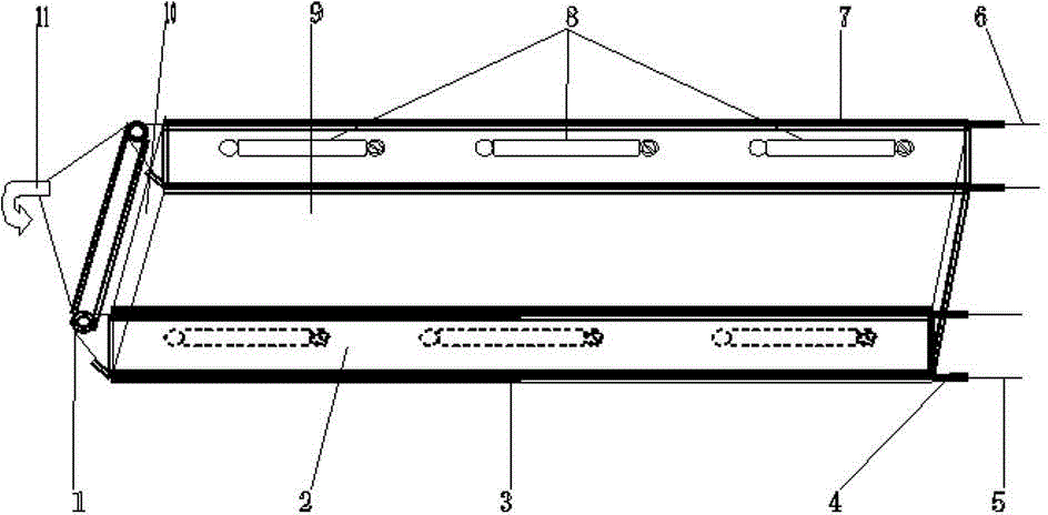
[0019] As shown in the accompanying drawings, the multifunctional safe and fast rescue chute of the present invention includes two parts: a main body and an accessory.
[0020] The main body includes a rope tube 1, a side rib 2, a lower collar 3, an upper collar 7, a groove bottom plate 9, and a transverse rib 10. Pulleys are provided at both ends to place the leash, and its function is to support the pulley and place the upper and lower leashes. The side ribs 2 are connected to both sides of the groove bottom plate 9, and their functions are to block and set the upper and lower retractors and safety Belt 8, the lower leash 3 is connected to the lower side of the side rib 2, and its function is to form a sleeve shape to allow the lower leash 5 to slide therein, and the upper leash 7 is connected to the upper side of the side rib 2, and its function It is to form a sleeve shape to allow the upper leash 6 to slide therein. The groove bottom plate 9 is connected to the inner side...
PUM
Abstract
The invention discloses a multifunctional safety and convenience conveying and rescuing groove, and relates to a conveying and rescuing device. The multifunctional safety and convenience conveying and rescuing groove comprises main components and auxiliaries including a rope looping pipe, side barriers, lower pull sleeves, upper pull sleeves, a groove bottom plate, a cross barrier, positioning clamps, lower pull ropes, upper pull ropes, safety belts, a safety hook and the like. The rope looping pipe is arranged at the front end of the conveying and rescuing groove, the side barriers are connected to two sides of the groove bottom plate, the lower pull sleeves are connected to the lower sides of the side barriers, the upper pull sleeves are connected to the upper sides of the side barriers, the groove bottom plate is connected to the inner sides of the side barriers, one side of the cross barrier is connected with the upper side of the groove and the inner sides of the side barriers respectively, the positioning clamps are arranged at heads of two ends of each of the upper pull sleeve and the lower pull sleeve and on the upper pull ropes and the lower pull ropes, the lower pull ropes are arranged on the inner sides of the lower pull sleeves, the upper pull ropes are arranged on the inner sides of the upper pull sleeves, the safety belts are arranged on the inner sides of the side barriers, and the safety hook is arranged on a loop rope at the front end of the rope looping pipe. The multifunctional safety and convenience conveying and rescuing groove is skillful in structural design, excellent in technical performance, multifunctional, high in practicability, convenient for conveying and rescuing, high-efficient, safe and durable, low in manufacturing and service cost, remarkable in comprehensive conveying and rescuing benefit.
Description
technical field [0001] The invention relates to a rescue chute, in particular to a multifunctional safe and fast rescue chute. Background technique [0002] For a long time, in the rescue process of force majeure natural disasters such as earthquakes and floods, due to the lack of corresponding effective transportation and rescue equipment, it has been difficult to complete the rescue and rescue of many people, property and animals that could have been quickly realized, especially for large-span and Difficult and urgent situations that cannot be directly rescued have no relatively safe, effective and fast support equipment for transportation and rescue, causing unnecessary losses to people's lives and property. For this reason, after long-term observation and research, the inventor has comprehensively considered the existing related facilities and technologies such as the lagging of the existing rescue technology, simple settings, single function, low safety, and poor rescue...
Claims
Application Information
Patent Timeline
Application Date:The date an application was filed.
Publication Date:The date a patent or application was officially published.
First Publication Date:The earliest publication date of a patent with the same application number.
Issue Date:Publication date of the patent grant document.
PCT Entry Date:The Entry date of PCT National Phase.
Estimated Expiry Date:The statutory expiry date of a patent right according to the Patent Law, and it is the longest term of protection that the patent right can achieve without the termination of the patent right due to other reasons(Term extension factor has been taken into account ).
Invalid Date:Actual expiry date is based on effective date or publication date of legal transaction data of invalid patent.