Plural-wire coiling device and plural-wire coiling method

A winding device and winding method technology, applied in the direction of electromechanical devices, coil manufacturing, motor generator manufacturing, etc., can solve problems such as difficulty in winding neatly, enlargement, etc., and achieve the effect of preventing the gap from expanding

Inactive Publication Date: 2013-01-09
NITTOKU ENG CO LTD
View PDF4 Cites 11 Cited by
  • Summary
  • Abstract
  • Description
  • Claims
  • Application Information

AI Technical Summary

Problems solved by technology

Then, the amount of deviation in the width direction of the wire drawn out from the nozzle or the pulley also increases during the period when it reaches the winding core, and the distance between the adjacent wires changes, making it difficult to wind neatly. bad situation
[0007] Especially when the winding core is thin and long, and the winding core is bent due to its length, the degree of deviation of the wire drawn out from the nozzle or the pulley duri

Method used


Image

  • Plural-wire coiling device and plural-wire coiling method
  • Plural-wire coiling device and plural-wire coiling method
  • Plural-wire coiling device and plural-wire coiling method

Examples


Embodiment Construction

[0034] Next, the best mode for implementing the present invention will be described based on the drawings.

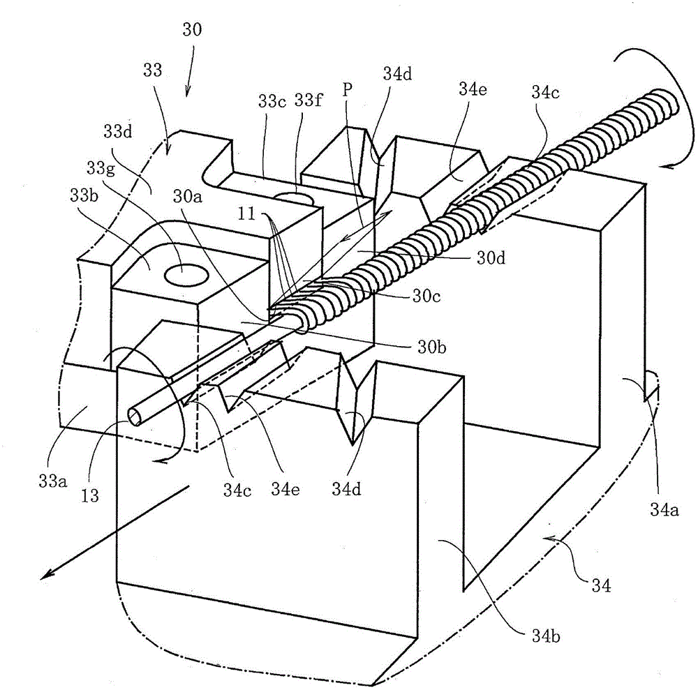
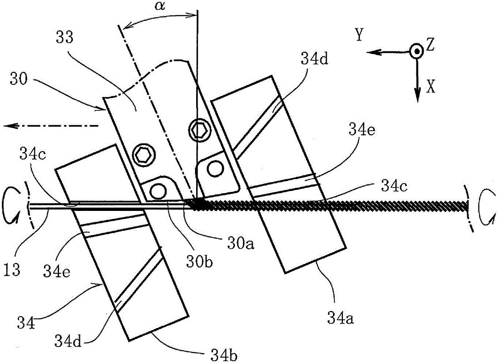
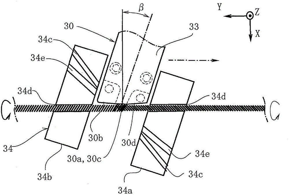
[0035] Such as Figures 12 to 14 As shown, the multi-wire winding device 10 of the present invention is a plurality of wires 11 ( Figure 14 ) is a device that is neatly wound on the outer periphery of the winding core 13 . As the winding core 13 in the figure, a case where a thin and long pin-shaped winding core having a circular cross section is used is shown. In addition, the winding core 13 is not limited to a winding core having a circular cross section, and may also be a winding core having a square cross section. Here, three axes X, Y, and Z that are orthogonal to each other are set. The X axis extends along the horizontal front and back direction, the Y axis extends along the horizontal horizontal direction, and the Z axis extends along the vertical direction. As for the device of the core 13, the multi-wire winding device 10 of the present invention will be d...


PUM


Abstract

The present invention provides a plural-wire coiling device and a plural-wire coiling method, wherein the plural-wire coiling device is provided with a coiling mechanism which enables a roll core to rotate about an axle and coils a wire led out by and passing through the opening of a wire hole, and a conveying mechanism enabling the wire hole or the roll core to move along the axle thereof; the plural-wire coiling device is also provided with a wire hole inclined rotation mechanism enabling the wire hole to obliquely rotate in a plane where the axle of the wire hole is parallel to the axle of the roll core, and a control mechanism for controlling the wire hole inclined rotation mechanism and enabling the inclined rotation angle of the wire hole to be in accord with an inclined angle endowed on the wire through the conveying mechanism to convey the wire hole or the roll core when the coiling mechanism is used for coiling the wire on the roll core. The shaped of the opening of the wire hole is oval or rectangular, such that the plural wires are arranged in a row to pass through the wire hole in the plane where the axle of the wire hole and the axle of the roll core are parallel to each other, and the front end edge of the wire hole from which the plural wires are output side by side in an inclined rotation state is formed, thereby enabling the plural wires to be arranged along the roll core.

Description

[0001] The invention relates to a multi-wire winding device and a multi-wire winding method for neatly winding a plurality of wires on the outer periphery of a winding core. Background technique [0002] Conventionally, as a technique for neatly winding a plurality of wires around the outer periphery of a winding core, there is known a winding device that uses a plurality of nozzles or pulleys corresponding to the number of the wires, and winds each wire from the plurality of wires. A plurality of wires drawn out from a nozzle or a pulley are wound around an outer periphery of a winding core that rotates around an axis (for example, refer to Patent Documents 1 and 2). In addition to the unit that rotates the winding core, these winding devices also have other units that rotate or move a plurality of nozzles or pulleys, and use this other unit to rotate or move a plurality of nozzles or pulleys, thereby eliminating the need for each of these nozzles or pulleys. The gap between ...

Claims


Application Information

Patent Timeline
IPC IPC(8): H01F41/06H02K15/04
Inventor 武藤宪一原英男
Owner NITTOKU ENG CO LTD
Why Eureka
Try Eureka