Power-source placement on electrically motorised bicycle

A technology of electric bicycles and electric motors, applied to bicycle frames, bicycle accessories, vehicle parts, etc., can solve the problem that bicycles cannot be assembled

Active Publication Date: 2013-01-09
PRO MOVEC
View PDF3 Cites 6 Cited by
  • Summary
  • Abstract
  • Description
  • Claims
  • Application Information

AI Technical Summary

Problems solved by technology

For example, a bicycle that lacks a carrier cannot be fitted with aftermarket modifications that have a b

Method used


Image

  • Power-source placement on electrically motorised bicycle
  • Power-source placement on electrically motorised bicycle
  • Power-source placement on electrically motorised bicycle

Examples


Example Embodiment

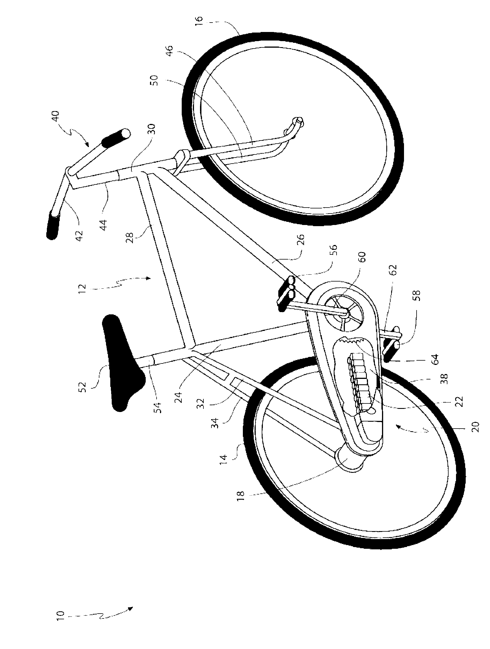
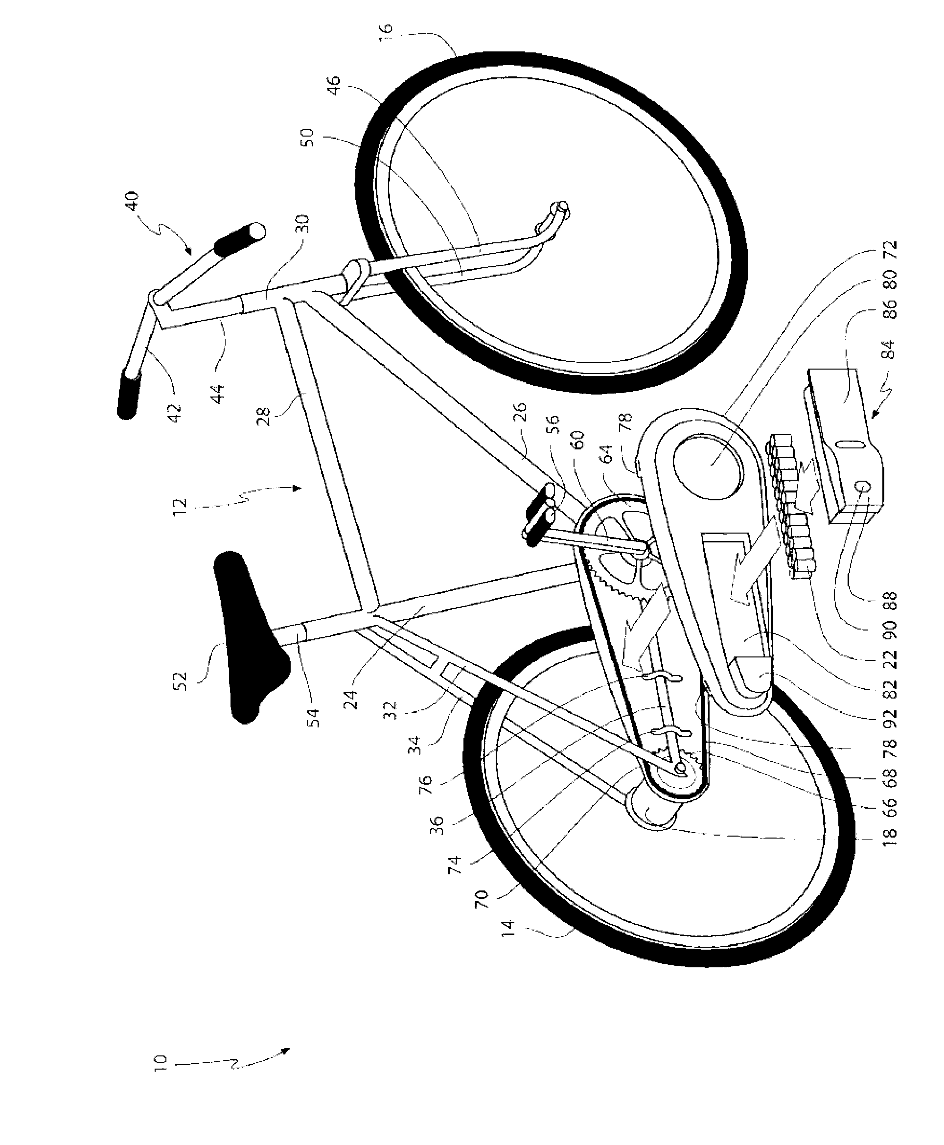
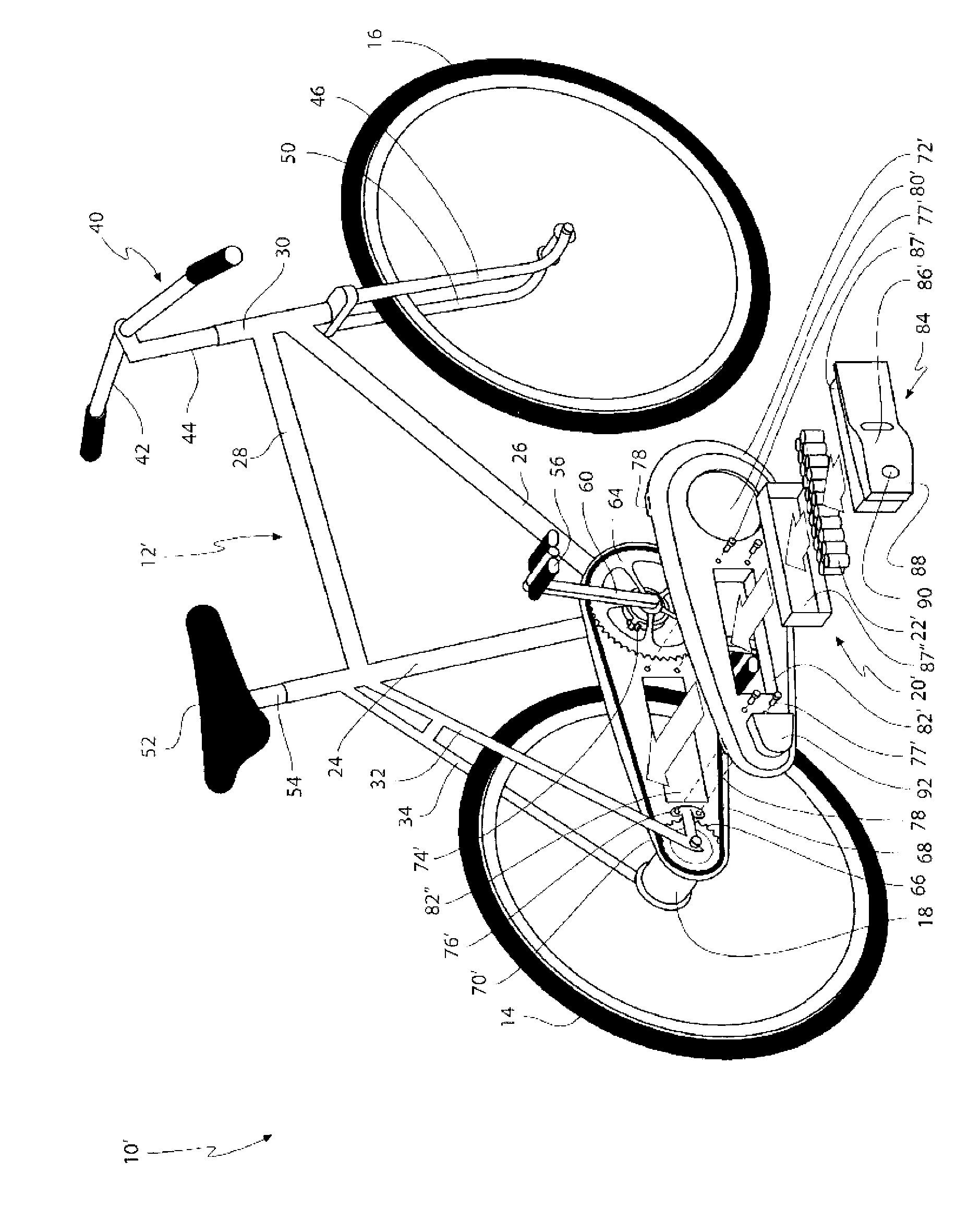
[0047] figure 1 An electric bicycle 10 according to a preferred embodiment of the present invention is shown. The electric bicycle 10 has a frame 12 rotatably connected to a rear wheel 14 and a front wheel 16. The rear wheel acts as a driving wheel when pedaling the bicycle. The brushless DC hub motor 18 is positioned at and centered on the hub of the rear wheel 14. The driving of the in-wheel motor 18 is powered and controlled by the driving unit 20. The drive unit 20 is shown as some parts of it are transparent to show a plurality of battery cells 22, which are rechargeable lithium ion batteries. The plurality of battery cells 22 supply power to the in-wheel motor 18.

[0048] The frame 12 has a seat tube 24, a down tube 26, a head tube 30, and an upper tube 28 connected in a closed loop in the listed order. The seat tube 24, the right chain stay 32, and the right chain stay 36 are connected in a closed loop in the order listed. Similarly, the seat tube 24, the left chain ...


PUM


Abstract

A drive unit (20) for a motorised bicycle (10) adapted to be at least partly powered by an electrical motor (18) is disclosed. The drive unit (20) comprises: a battery pack (84) including one or more battery cells (22) for providing the electrical motor with electrical energy, and a battery pack support (70, 72) for connecting the battery pack to the frame (12), where the battery pack support and the battery pack are adapted for positioning a battery cell of the one or more battery cells between the first (64) and second (66) sprockets of the motorised bicycle.

Description

technical field [0001] The present invention relates generally to electric bicycles powered by electric motors. More specifically, the present invention relates to battery packs for electric motors, and in particular to the positioning of the battery cells of the battery pack. Background technique [0002] An electric bicycle is a bicycle that has an electric motor used to power the vehicle or to assist in pedaling. The electric motor is attached to the bicycle during construction of the bicycle, or after construction of the bicycle as an aftermarket modification. The difference between electric bicycles and motorcycles is that they can be powered by pedals alone. Some e-bikes use pedals as the main form of propulsion, with the electric motor used to provide extra power, for example when going uphill, while others can be driven solely by their respective electric motors. [0003] Many e-bikes are based on a standard bike frame, for example they have a frame with a seat tu...

Claims


Application Information

Patent Timeline
IPC IPC(8): B62J13/04B62K19/44B62M6/90
CPCB62M6/90B62J13/04B62K19/40B62M6/60B62J43/13B62J43/20
Inventor J·拉斯姆森
Owner PRO MOVEC
Why Eureka
Try Eureka