Fluid collection and disposal system and related methods

Active Publication Date: 2011-05-19
ALLEGIANCE CORP
View PDF114 Cites 8 Cited by
  • Summary
  • Abstract
  • Description
  • Claims
  • Application Information

AI Technical Summary

Benefits of technology

[0007]Among others, various aspects of the invention may include providing a fluid collection system that utilizes disposable flexible liners to reduce the volume of medical wastes. Another aspect may include providing a lid for a fluid collection system that automatically connects to a suction source. Also, certain aspects of the invention may provide a waste disposal system, for use with the fluid collection system that may improve labor efficiency, safety, and convenience of the medical personnel participating in a medical procedure. In particular, the fluid collection systems and waste disposal systems in accordance with aspects of the present invention may provide a clean and convenient interface between the source of waste and the waste disposal station, thereby reducing the risk of exposure to potentially hazardous waste.
[0010]The shelf may be located between the first opening and the second opening, wherein the shelf extends from a surface of the lid a sufficient distance to divert collected fluids away from the access port of the suction source. The shelf may be shaped to direct fluid entering the first opening toward the liner. The fluid collection container may further include a screen formed on the surface of the lid facing the liner surrounding the evacuation port, and the shelf may be further shaped to prevent the liner from collapsing against at least a portion of the screen during removal of the collected fluid.

Problems solved by technology

This process can be labor intensive and time consuming.
Furthermore, since this process is performed following every medical procedure, the frequency of the process may increase the clinicians' risk of exposure to potentially hazardous waste.

Method used


Image

  • Fluid collection and disposal system and related methods
  • Fluid collection and disposal system and related methods
  • Fluid collection and disposal system and related methods

Examples


Embodiment Construction

[0038]Reference will now be made in detail to aspects of the present invention, examples of which are illustrated in the accompanying drawings. Wherever possible, the same reference numbers will be used throughout the drawings to refer to the same or like parts.

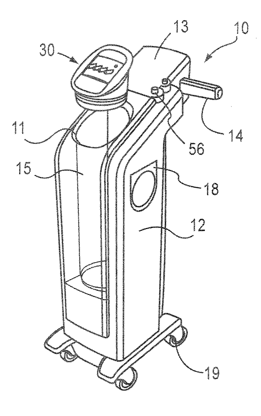
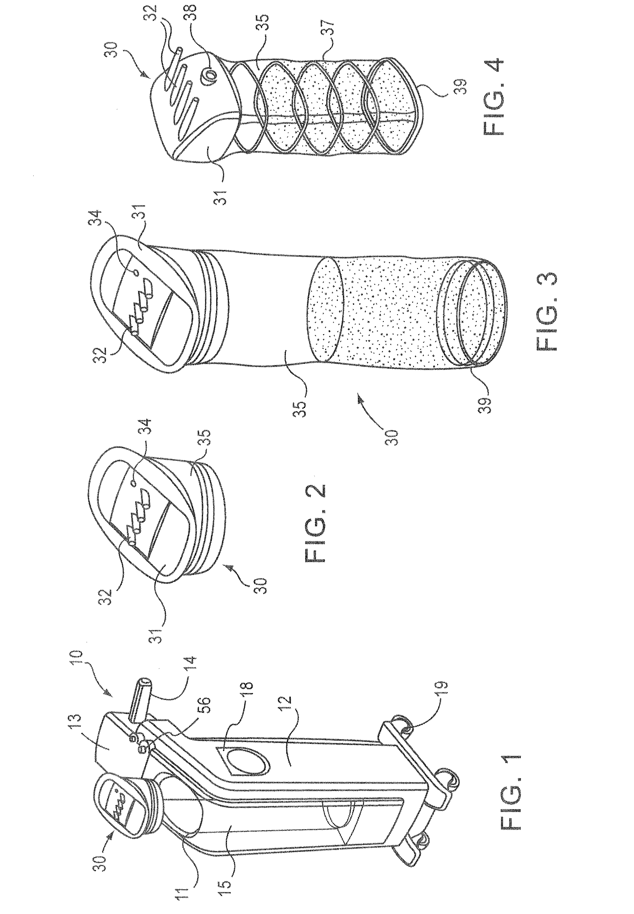
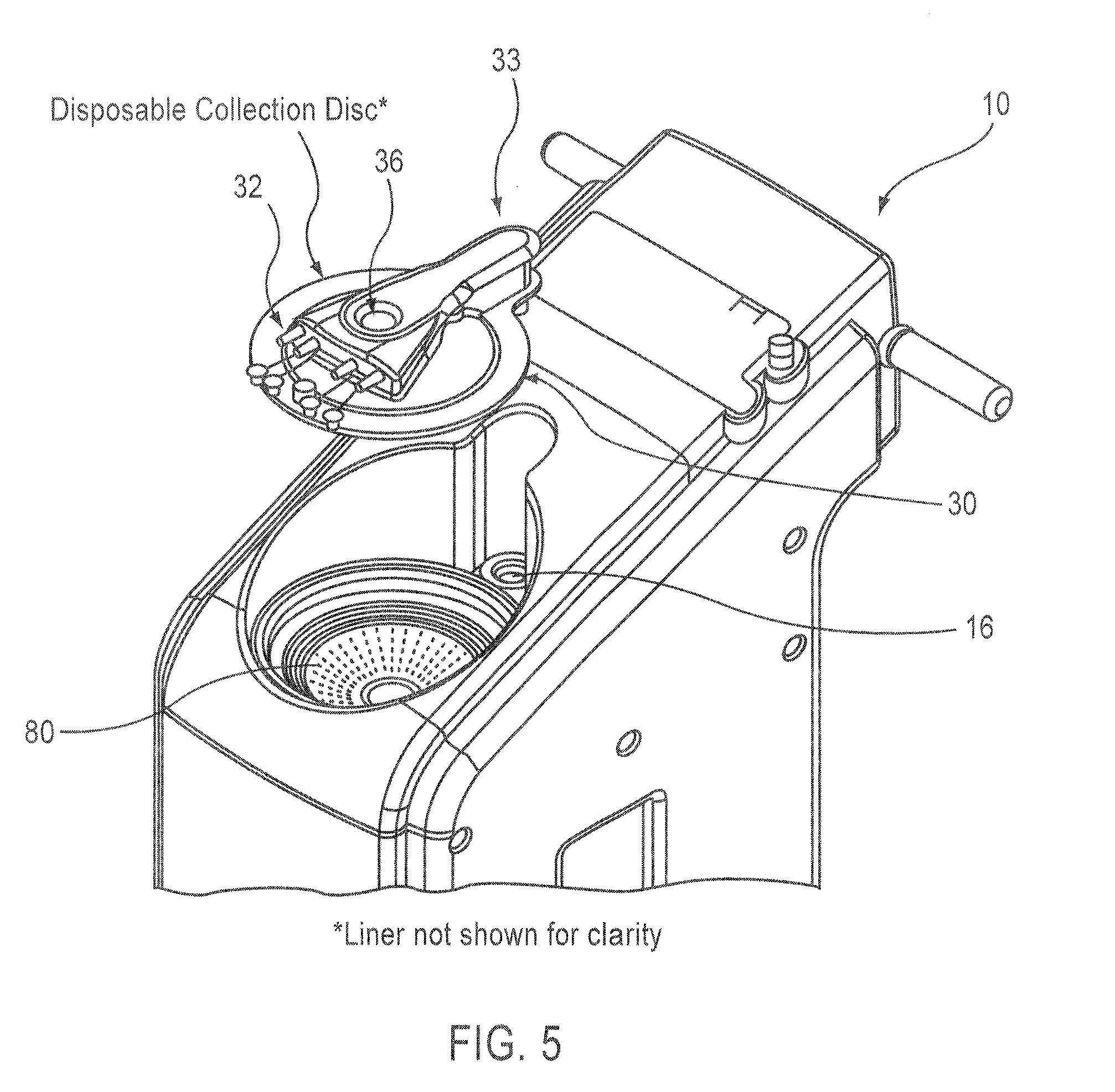
[0039]FIGS. 1-5 show a portable fluid collection system 10 (herein also referred to interchangeably as a liquid collection system), according to exemplary aspects of the present invention. The portable fluid collection system may include any of the aspects described in co-pending application Ser. No. 12 / 076,842 filed on Mar. 24, 2008, titled LIQUID COLLECTION AND DISPOSAL SYSTEM AND RELATED METHODS or application Ser. No. 12 / 076,841 filed on Mar. 24, 2008, titled FLUID COLLECTION AND DISPOSAL SYSTEM HAVING INTERCHANGEABLE COLLECTION AND OTHER FEATURES AND METHODS RELATING THERETO, the entire contents of both of which are incorporated herein by reference

[0040]The system 10 includes a main body, also interchangeably referred to...


PUM

PropertyMeasurementUnit
Massaaaaaaaaaa
Pressureaaaaaaaaaa
Molecular weightaaaaaaaaaa

Abstract

A fluid collection system includes a disposable collection container and a disposable collection container receiving housing, the housing having a cavity and a suction source. The fluid collection container may include a flexible liner and a shelf for diverting fluid from the suction and to assist with a collapse of the liner during evacuation of the fluid from the liner. The collection container receiving housing may include a piston assembly having a main piston body and a scraper ring. The collection container receiving housing may include a piston stop feature. The system may include a partially hydrophobic filter and a flat surface suction tool.

Description

CLAIM OF PRIORITY UNDER, 35 U.S.C. §119[0001]This application claims the benefit of U.S. Provisional Application Ser. No. 61 / 225,812, entitled “FLUID COLLECTION AND DISPOSAL SYSTEM AND RELATED METHODS” and filed on Jul. 15, 2009, which is expressly incorporated by reference herein in its entirety.BACKGROUND OF THE INVENTION[0002]1. Technical Field of the Invention[0003]Aspects of the present invention relate generally to fluid collection and disposal systems and related methods. More specifically, particular aspects relate to liquid collection and disposal systems that utilize flexible liners and related methods of use thereof.[0004]2. Brief Description of Related Art[0005]Hospital operating rooms, emergency rooms, and other healthcare facilities generate a large volume of liquid waste, which may include irrigation liquids and secretions removed from a patient's body (e.g., blood and other bodily liquids). To collect and dispose of such liquid waste, suction canisters are typically ...

Claims


Application Information

Patent Timeline
IPC IPC(8): A61M1/00
CPCA47L5/365A61M1/0052A47L7/0038A47L7/0042A47L9/1418A61M1/0001A61M1/0005A61M27/00A61M2205/7536A61M2209/084B08B13/00A61M1/0023A61M1/0017A61M1/005A47L7/0028Y10T137/86083A61M1/604A61M1/602A61M1/63A61M1/782A61M1/784A61M1/743A61M1/79A61M1/60A61M1/732
Inventor MICHAELS, THOMAS L.JOHNSON, RUSS A.HILL, ERIC D.
Owner ALLEGIANCE CORP
Why Eureka
Try Eureka