Flying shear device for finishing and shearing of thick metal strips

A strip and metal technology, which is applied in the field of flying shear device for trimming and shearing thick metal strips, can solve the problems of low production efficiency, small shear thickness range, and slow shear speed, etc., and achieve high production efficiency, The effect of increasing shear frequency and improving machining accuracy

Inactive Publication Date: 2013-01-16
辽宁省机械研究院有限公司
View PDF8 Cites 8 Cited by
  • Summary
  • Abstract
  • Description
  • Claims
  • Application Information

AI Technical Summary

Problems solved by technology

However, with the improvement of related technology and the continuous improvement of production requirements, the existing flying shears

Method used


Image

  • Flying shear device for finishing and shearing of thick metal strips
  • Flying shear device for finishing and shearing of thick metal strips
  • Flying shear device for finishing and shearing of thick metal strips

Examples


Example Embodiment

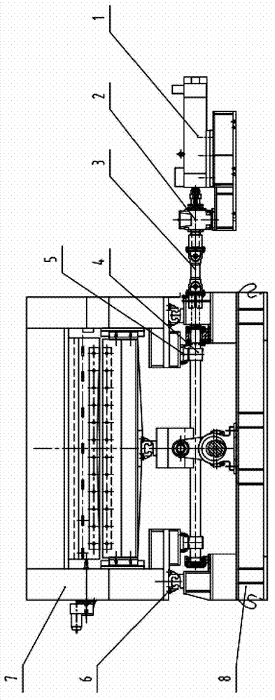
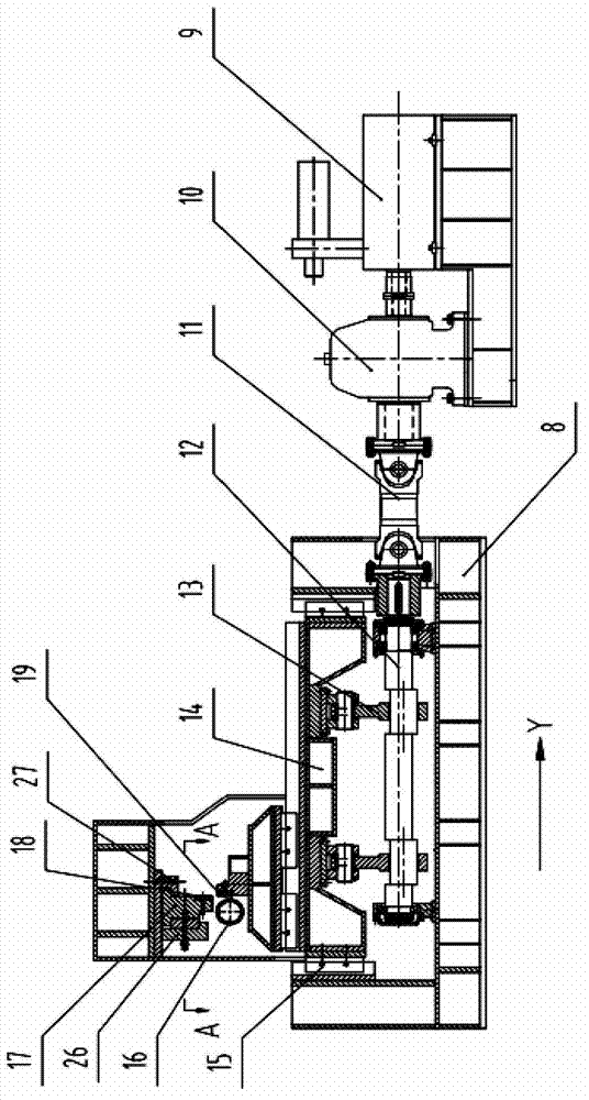
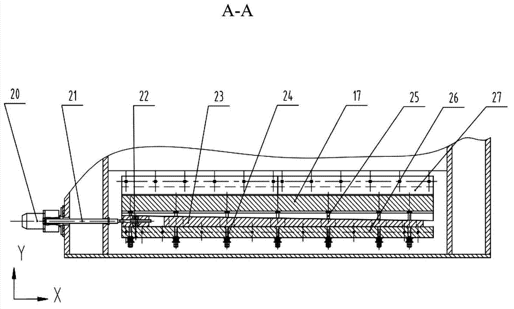
[0015] The flying shear device provided by the present invention is mainly composed of a main driving device, an eccentric link type shearing device and a knife body gap adjustment device, wherein the main driving device includes: a main drive motor 1, a main drive reducer 2, a main drive Drive coupling 3, main drive gear shaft 4, main drive rack 5, main drive linear guide 6, beam 7 and base 8; eccentric link type shearing device includes: shearing motor 9, shearing reducer 10, Shear coupling 11, shear eccentric shaft 12, shear connecting rod 13, lower shear seat 14, shear linear guide 15, shear roller 16, upper shear clamp 17, upper knife body 18 and lower knife body 19 The knife body clearance adjustment device includes: a clearance adjustment motor 20, a clearance adjustment screw 21, a clearance adjustment nut 22, a diagonal wedge adjustment pad 23, a disc spring 24, a T-shaped screw 25, a lower pressing plate 26 and an upper pressing plate 27.

[0016] In an exemplary embodi...


PUM


Abstract

The invention discloses a flying shear device for finishing and shearing of thick metal strips. The flying shear device mainly comprises a main driving device, a shearing device and a cutter clearance adjusting device. A main driving motor is connected with a shearing eccentric shaft through a speed reducer and a coupling, lower ends of two shearing links are mounted on the shearing eccentric shaft, upper ends of the two shearing links are fixedly connected with a lower shear holder, a lower cutter is fixed on the lower shear holder, an upper cutter is fixed on an upper shearing clamp, the upper shearing clamp is fixed on a base, and the cutter clearance adjusting device is used for adjusting clearance between the cutters. The flying shear device can realize high-speed continuous shearing operation. Compared with a general flying shear, the flying shear device has the advantages that the shearing speed of the flying shear device is increased by two to three times, the shearing precision is increased by two to four times, and shearing burrs and curls are eliminated thoroughly.

Description

technical field [0001] The invention relates to the metallurgical machinery industry, in particular to a flying shear device for trimming and cutting metal thick plate strips. Background technique [0002] In the field of metallurgical finishing industry, especially in the thick plate transverse shearing production line, hydraulic shearing flying shears are often used equipment for continuous fixed-length shearing of the leveled plate. However, with the improvement of related technology and the continuous improvement of production requirements, the existing flying shears generally have shortcomings such as low production efficiency, small shear thickness range, and slow shear speed. The structure is improved. Contents of the invention [0003] The purpose of the present invention is to design a flying shear device for trimming and shearing metal thick plate strips. Compared with the existing flying shear equipment, the flying shear device can increase the shearing speed a...

Claims


Application Information

Patent Timeline
IPC IPC(8): B23D25/02B23D33/00
Inventor 陈立停王建珩王蔷霍丹李慧李蕾佟文华
Owner 辽宁省机械研究院有限公司
Why Eureka
Try Eureka