Railroad track scale sensor and producing method thereof

A manufacturing method and sensor technology, applied in the field of rail scales, can solve the problems of high cost, difficult mass production, complex installation requirements, etc., and achieve the effects of long working life, fast dynamic response, and wide testing range.

Inactive Publication Date: 2013-01-16
福建省莆田市衡力传感器有限公司
View PDF5 Cites 4 Cited by
  • Summary
  • Abstract
  • Description
  • Claims
  • Application Information

AI Technical Summary

Problems solved by technology

[0002] Traditional track weighing sensors have complex structures and are mainly installed at the bottom of static and dynamic track weighing platforms, and then calculate the weight through the analog-to-digital conversion of secondary instruments and computers. The installation requirements are complex, and the original track of the enterprise needs to be modified. The installation and testing of track scales must consume a lot of time and cost, and it is impossible to realize dynamic vehicle weighing. The cost is high, and it has gradually failed to meet the requirements of high tonnage, high precision, and non-standardized tracks. At the same time, traditional track scales are mostly static vehicles. Weighing, it is difficult to accurately park the car at the position to be detected in actual operation, so the application range is narrow and the efficiency is low
At the same time, limited by the complexity of the structure, the production process of the traditional track load cell is complicated, the cost is high, and it is not easy to mass-produce. In addition, the products made by the traditional method have insufficient temperature control and stress treatment, and the creep of the elastomer is too high, which is safe. Very low overload and ultimate overload capabilities

Method used


Image

  • Railroad track scale sensor and producing method thereof
  • Railroad track scale sensor and producing method thereof
  • Railroad track scale sensor and producing method thereof

Examples


Embodiment Construction

[0042] In order for those skilled in the art to further understand the features and technical content of the present invention, please refer to the following detailed description and accompanying drawings of the present invention.

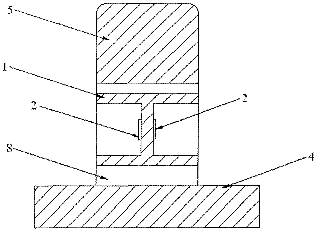
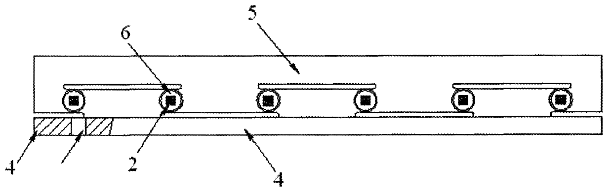
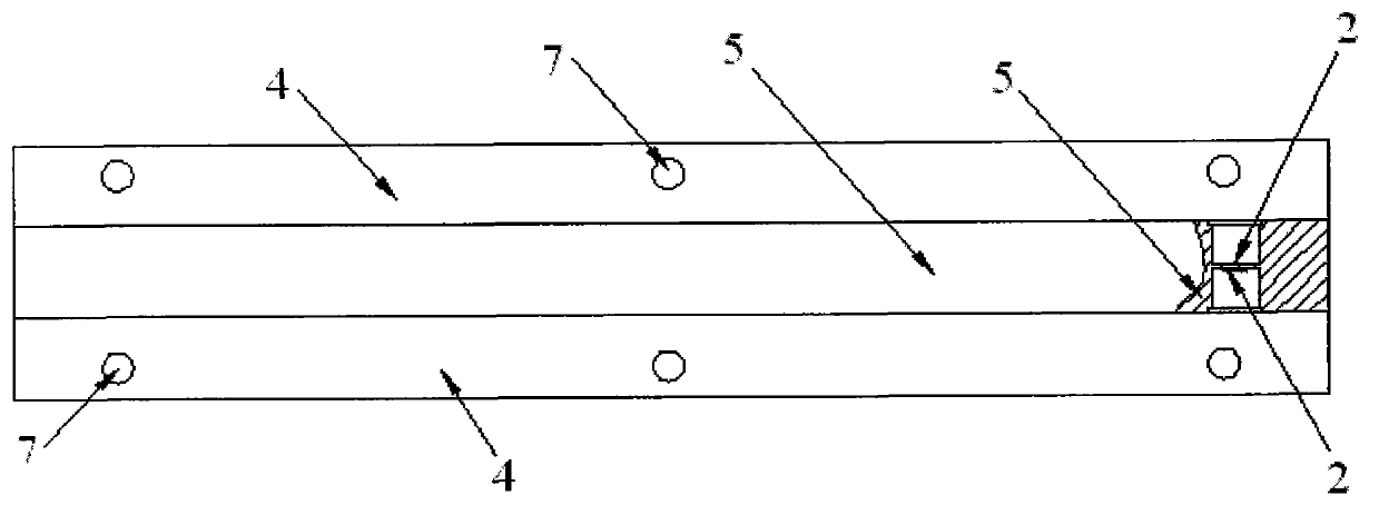
[0043] see Figure 1 to Figure 4 As shown, the present invention provides a rail scale sensor, including elastic body 1, strain resistance 2 and wire 3 connected in sequence, wherein, the longitudinal section of the elastic body is "I" shape, and the strain resistance is at least one Each group of strain resistors is divided into two parts and bonded to symmetrical positions on both sides of the waist of the elastic body. The strain resistors in each part are at least 4 pieces and are connected into a bridge circuit through the wires , the strain resistances of each part are connected in parallel, and also include an inverted "T"-shaped track body in the longitudinal section formed by the base 4 and the support beam 5 connected to the base, and the...


PUM


Abstract

The invention discloses a railroad track scale sensor which comprises an elastic body, at least one group of strain resistors and leads which are sequentially connected. The longitudinal section of the elastic body is 'H'-shaped, each group of strain resistors is divided into two portions and adhered to symmetrical positions of two sides of the waist of the elastic body, each portion is composed of at least four strain resistors which are connected by the leads to form a bridge circuit, and the strain resistors in each portion are parallelly connected. The invention further discloses a producing method of the railroad track scale sensor. The method includes the steps: providing the elastic body with the 'H'-shaped longitudinal section; providing at least one group of strain resistors, wherein each group of strain resistors is divided into two portions and adhered to symmetrical positions of two sides of the waist of the elastic body, and each portion includes at least four strain resistors; and providing the leads and connecting the strain resistors through the leads to from the bridge circuit. The railroad track scale sensor is simple in structure, easy to mount and high in measuring precision, and the method is low in cost and easy to produce.

Description

technical field [0001] The invention relates to the field of rail scales, in particular to a rail scale sensor and a manufacturing method thereof. Background technique [0002] Traditional track weighing sensors have complex structures and are mainly installed at the bottom of static and dynamic track weighing platforms, and then calculate the weight through the analog-to-digital conversion of secondary instruments and computers. The installation requirements are complex, and the original track of the enterprise needs to be modified. The installation and testing of track scales must consume a lot of time and cost, and it is impossible to realize dynamic vehicle weighing. The cost is high, and it has gradually failed to meet the requirements of high tonnage, high precision, and non-standardized tracks. At the same time, traditional track scales are mostly static vehicles. Weighing, it is difficult to accurately park the car at the position to be detected in actual operation, ...

Claims


Application Information

Patent Timeline
Patent Type & Authority Applications(China)
IPC IPC(8): G01G19/04
Inventor 陈立成彭志坚
Owner 福建省莆田市衡力传感器有限公司
Why Eureka
Try Eureka