Field dynamic load testing method for collision resistance and safety of highway corrugated beam barriers

A corrugated beam guardrail and detection method technology, which is applied in the direction of measuring device, impact test, machine/structural component test, etc., can solve the problems of high experiment cost, safety performance evaluation of guardrail, etc., and achieve lower test cost, true results and better detection Easy to operate and fast effect

Active Publication Date: 2014-12-24
CHINA MERCHANTS CHONGQING COMM RES & DESIGN INST
View PDF4 Cites 2 Cited by
  • Summary
  • Abstract
  • Description
  • Claims
  • Application Information

AI Technical Summary

Problems solved by technology

Although the full-scale crash test method is recognized as the most direct and effective method, it can only be carried out in the laboratory, and it is a destructive test, the cost of the test is extremely high, and the results of the test are difficult to evaluate the safety performance of the guardrail on the engineering site
Although computer simulation has high theoretical guiding significance, the consistency with the actual road safety system still needs to be tested in practice

Method used


Image

  • Field dynamic load testing method for collision resistance and safety of highway corrugated beam barriers
  • Field dynamic load testing method for collision resistance and safety of highway corrugated beam barriers

Examples


Embodiment 1

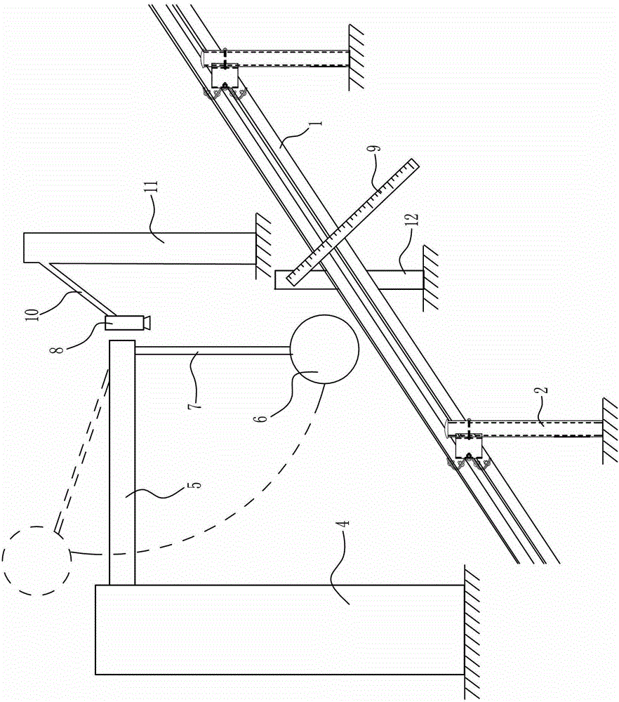
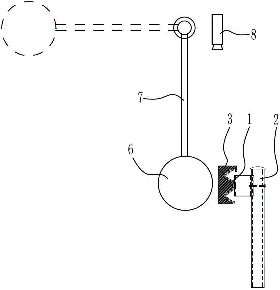
[0028] 1) Select the midpoint of the wave beam guardrail 1 between two adjacent columns 2 as the impact point, and install a steel coupling block 3 at the impact point. The steel coupling block 3 is located inside the wave beam guardrail 1 (facing the road on the side of the side). The steel coupling block 3 is a square structure, and there is a wave-shaped groove on the surface of the steel coupling block 3 facing the wave beam guardrail 1. The shape and size of the wave-shaped groove adapt to the section of the wave beam guardrail 1, and the wave The inner surface of the groove and the steel coupling block 3 is fully fitted. The steel coupling block 3 can be hooked on the corrugated beam guardrail 1 through the hook provided at its upper end, and the steel coupling block 3 can also be snapped on the corrugated beam guardrail 1 through the buckles provided at its upper and lower ends. Of course, as an equivalent replacement, the steel coupling block 3 can also be connected t...

Embodiment 2

[0034] In step 4) of this embodiment, a cast iron block is selected as the heavy object, and the cast iron block hits the steel coupling block 3 under the action of the elastic force of the ejection device. The rest of the steps in this embodiment are the same as those in Embodiment 1, and will not be repeated here. The specific structure of the ejection device can be selected from existing structures according to actual needs, as long as it can provide elastic force to the weight.

Embodiment 3

[0036] In step 4) of this embodiment, the heavy object is a steel column, and the steel column hits the steel coupling block 3 under the action of the traction force of the traction device. The rest of the steps in this embodiment are the same as those in Embodiment 1, and will not be repeated here. The specific structure of the traction device can be selected from existing structures according to actual needs, as long as it can provide traction to the heavy objects.


PUM


Abstract

The invention discloses a field dynamic load testing method for collision resistance and safety of highway corrugated beam barriers. The method comprises the steps of selecting a collision point; arranging a steel coupling block, a high-speed camera and a displacement measurement scale; colliding a weight against the steel coupling block to obtain measurement results and the like. According to the field dynamic load testing method for collision resistance and safety of highway corrugated beam barriers, safety performances of highway corrugated beam barriers can be tested in the engineering field, and the testing method is not limited by places and highway conditions; and not only the implementation cost is low, but also the testing operation is convenient and rapid, the testing efficiency is high, and testing results are accurate and reliable. The field dynamic load testing method can help highway operation management units grasp security performances of traffic safety facilities of governed highway sections, and can also serve as an approach for quality supervision units to supervise and check barrier construction quality randomly.

Description

technical field [0001] The invention belongs to the technical field of road traffic, and in particular relates to a method for on-site measurement of the safety performance of a road wave-beam guardrail, which is mainly used for on-site measurement of the safety performance of a road wave-beam guardrail. Background technique [0002] While my country's highways are promoting the rapid development of the national economy, the high incidence of highway traffic accidents and death rates have also brought many adverse effects to the rapid development of the economy, the continued stability of the society, and the safety of people's lives and properties. The guardrails of highways, especially expressways, are mainly corrugated beam steel guardrails. Many serious traffic accidents have occurred when vehicles smashed through the guardrails and rushed out of the road. Therefore, the safety performance of the guardrail is of great significance to the protection of traffic safety. ...

Claims


Application Information

Patent Timeline
Patent Type & Authority Patents(China)
IPC IPC(8): G01M7/08
Inventor 邹小春须民健郭兴隆付立家陈晓利田川李茂华韩直苏宇峰周广振袁源谢耀华秦茂昭
Owner CHINA MERCHANTS CHONGQING COMM RES & DESIGN INST
Why Eureka
Try Eureka