Three-electrode trigger switch

A trigger switch, three-electrode technology, applied to spark gaps, circuits, electrical components with auxiliary trigger devices, etc., can solve the problems of high cost, complex application scope and process, and achieve uniform electric field distribution, dielectric strength recovery, and dispersion. small effect

Active Publication Date: 2013-01-16
STATE GRID CORP OF CHINA +1
View PDF6 Cites 14 Cited by
  • Summary
  • Abstract
  • Description
  • Claims
  • Application Information

AI Technical Summary

Problems solved by technology

However, this patent only involves a three-electrode discharge switch in a vacuum environment, and its application range is limited, and the process is complicated and the cost is high.

Method used


Image

  • Three-electrode trigger switch
  • Three-electrode trigger switch

Examples


Embodiment Construction

[0019] In order to better understand the present invention, the content of the present invention is further illustrated below in conjunction with the examples, but the content of the present invention is not limited to the following examples. Those skilled in the art can make various changes or modifications to the present invention, and these equivalent forms are also within the scope of the claims listed in this application.

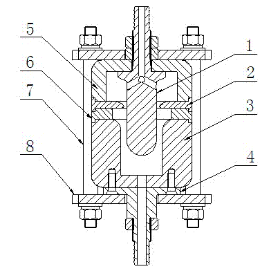
[0020] Explanation of marks in the figure: 1-anode electrode, 2-trigger electrode, 3-cathode electrode, 4-cathode seal, 5-insulation cover, 6-insulation spacer, 7-insulation fastening rod, 8-insulation fastening pressure plate .

[0021] Take a 10kV three-electrode trigger switch as an example, such as figure 1 As shown, it consists of copper anode electrode 1, cathode electrode 3, trigger electrode 2, cathode seal 4, polytetrafluoroethylene insulation cover 5, insulation spacer 6, nylon insulation fastening rod 7 and insulation fastening pressure pla...


PUM


Abstract

The invention discloses a three-electrode trigger switch. The three-electrode trigger switch is of a coaxial structure, and comprises a positive electrode, negative electrodes, trigger electrodes, negative sealing elements, insulation covers and insulation separators. The insulation cover is used for insulating and fixing electrodes, and various parts are compressedly sealed by an insulation fastening rod and an insulation fastening pressure plate. A gas inlet channel used for discharging gas is arranged inside the positive electrode, high pressure gas flows past trigger gaps to bring charged particles produced by the trigger gaps into a main switch gap, so that the main gap under high pressure is communicated. The high pressure gas brings the charged particles produced by discharging of the trigger gaps out of the switch through gas outlet through holes at the bottom of the negative electrodes and gas outlet channels of the negative sealing elements, insulation strength recovering of the switch is accelerated, a corresponding trigger system is matched, and the switch can be used with repetition frequency. The three-electrode trigger switch is simple in structure and high in working stability and can be applicable to various impulse power supplies.

Description

technical field [0001] The invention relates to a three-electrode trigger switch, which is especially suitable for a switch component for a pulse power supply, and belongs to the technical field of high-voltage switch manufacturing and pulse power. Background technique [0002] With the rapid development of pulse power technology, many economic and military powers have joined the research in this field, and the switch is the most important part of the entire pulse source, and its performance directly affects the output performance of the entire device. Semiconductor switching devices such as IGBTs and thyristors can achieve high repetition rates under operating voltages, but due to their poor withstand voltage and current capabilities, they are difficult to use in high-voltage and high-power pulse sources. The gas switch has a simple structure, is easy to process, and can easily achieve a higher operating voltage (such as megavolts) and a larger conduction current. However, ...

Claims


Application Information

Patent Timeline
Patent Type & Authority Applications(China)
IPC IPC(8): H01T2/02H01T1/00
Inventor 姜春阳周峰拉贵
Owner STATE GRID CORP OF CHINA
Why Eureka
Try Eureka