Converter for an electrical machine, controller and method for operating a converter

一种逆变器、控制器的技术,应用在电动机控制、交流电动机控制、交流电动机的减速装置等方向,能够解决保护装置制造成本和所需空间大等问题,达到节约所需空间、节约制造费用的效果

Inactive Publication Date: 2013-01-16
MAGNA POWERTRAIN GMBH & CO AG
View PDF6 Cites 14 Cited by
  • Summary
  • Abstract
  • Description
  • Claims
  • Application Information

AI Technical Summary

Problems solved by technology

In addition to reducing the torque which is not the aim of the measure proposed in DE 298 13 080 U1 (short-circuiting the phases to each other), the protective device proposed in DE 298 13 080 U1 is also expensive to manufacture and requires a lot of space

Method used


Image

  • Converter for an electrical machine, controller and method for operating a converter
  • Converter for an electrical machine, controller and method for operating a converter
  • Converter for an electrical machine, controller and method for operating a converter

Examples


Embodiment Construction

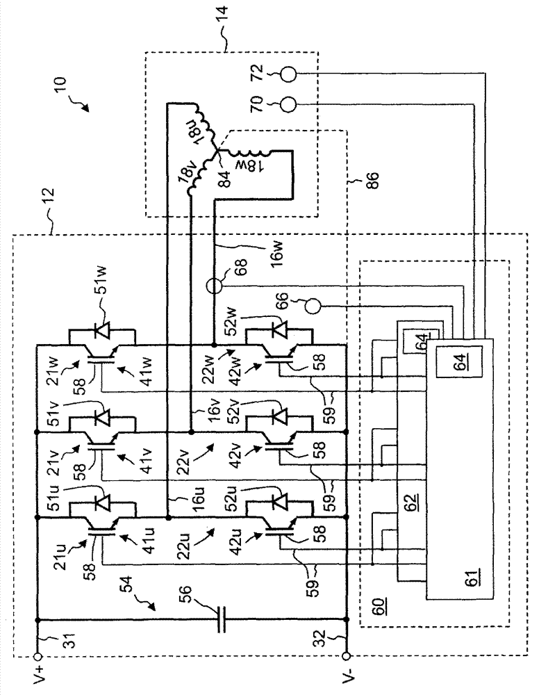
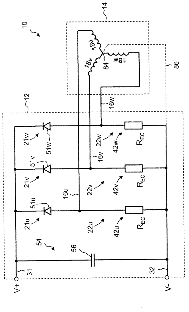
[0033] figure 1 The illustrated system 10 includes an inverter 12 and an electric motor 14 . The electric motor 14 is connected to the inverter 12 with three phase lines 16u, 16v, 16w. The motor 14 is permanently excited. The permanent magnets of the electric motor 14 (not shown in the accompanying drawings) are usually fixed in the rotor of the electric motor 14 (not shown in the drawings), and the windings 18u, 18v, 18w of the electric motor 14 are all arranged between the stators of the electric motor 14 middle. The drawing shows how the winding 18 is connected to the phase conductor 16 in a star connection. Another alternative, not shown in the figures, is to connect the winding 18 to the phase line 16 in a delta connection. The inverter 12 comprises a first switching circuit 21u, 21v, 21w per phase line 16 for temporarily connecting the phase line 16 with the supply line 31 having a positive potential V+. Furthermore, the inverter 12 also includes a second switching ...


PUM


Abstract

A converter for an electrical machine having a plurality of phase lines for connecting the electrical machine. For each phase line the converter has a half-bridge with a first first semiconductor switch is configured to electrically connect at least one of the phase lines intermittently to a first supply line of the converter, and a second semiconductor switch configured to electrically connect the phase line intermittently to a second supply line of the converter. The converter is configured for operation in a first energy recovery limiting mode in which at least two of the first semiconductor switches are at least intermittently on simultaneously.

Description

technical field [0001] The invention relates to an inverter for a motor, wherein the inverter comprises a plurality of phase lines for connecting the motor, wherein each phase line of the inverter comprises a first semiconductor switch and a A half-bridge of second semiconductor switches, wherein the first semiconductor switch is operable to temporarily electrically connect at least one phase line to the first power supply line of the inverter, and the second semiconductor switch is operable to temporarily connect the phase line to the inverter's The second power line is electrically connected. The first power line may be the positive power line of the inverter used to connect to the positive pole of the power supply; the second power line is the negative power line of the inverter used to be connected to the negative pole of the power supply. Alternatively, the first power line can also be a negative power line of the inverter used to connect to the negative pole of the powe...

Claims


Application Information

Patent Timeline
Patent Type & Authority Applications(China)
IPC IPC(8): H02P27/06
CPCB60L7/14H02P3/22H02P27/06Y02T10/642H02P29/024H02H7/122H02P29/0241Y02T10/64
Inventor T·菲克廷格W·保罗C·斯平德尔伯格J·坦恩海默
Owner MAGNA POWERTRAIN GMBH & CO AG
Why Eureka
Try Eureka