
Roller cutter for shredder, and shredder

A paper shredder and hob technology, applied in grain processing, etc., can solve the problem of increased working hours and achieve the effect of reducing metal materials

Inactive Publication Date: 2013-01-16
KOKUYO CO LTD
View PDF4 Cites 0 Cited by
  • Summary
  • Abstract
  • Description
  • Claims
  • Application Information

AI Technical Summary

Problems solved by technology

Therefore, as a result, there is a problem that man-hours in the manufacturing process of the shredder will increase anyway.

Method used


Image

  • Roller cutter for shredder, and shredder
  • Roller cutter for shredder, and shredder
  • Roller cutter for shredder, and shredder

Examples


no. 1 approach

[0060] A first embodiment of the present invention will be described below with reference to the drawings.

[0061] The shredder S according to the present embodiment is a so-called residential / SOHO shredder, and is suitable for home and / or small-scale offices called SOHO. Lift.

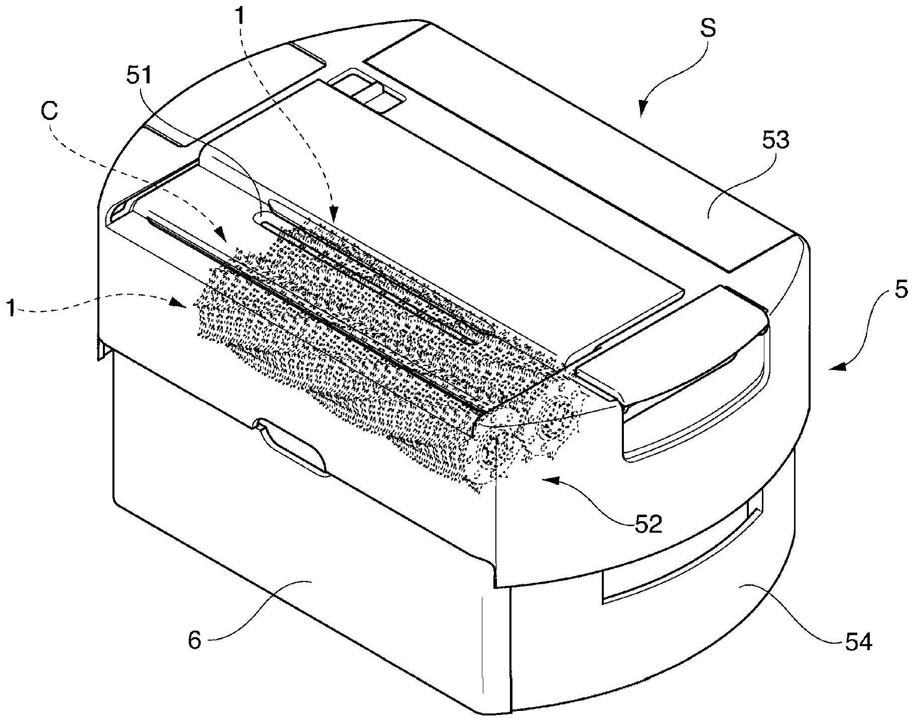
[0062] Such as figure 1 As shown, the paper shredder S mainly has: a single housing 5; a paper shredding mechanism C, which is used to shred paper and other shredded objects in the housing 5, which is indicated by a dotted line in the figure; A drawer-shaped chip container 6 that crushes chips and discharges them out of the casing 5 . In addition, the shredder S according to this embodiment is further provided with a drive mechanism for driving the shredder mechanism C, an operation unit having a main power switch, etc. The interlock mechanism and the like for making the crushing blade 3 inoperative are described below. However, since various existing configurations can be adopted for these compon...

no. 2 approach

[0097] Use below Figure 19 to Figure 26 Modifications of this embodiment will be described. Also in this second embodiment, as in the above-mentioned first embodiment, the same reference numerals are assigned to components corresponding to those in the above-mentioned embodiment, and detailed description thereof will be omitted.

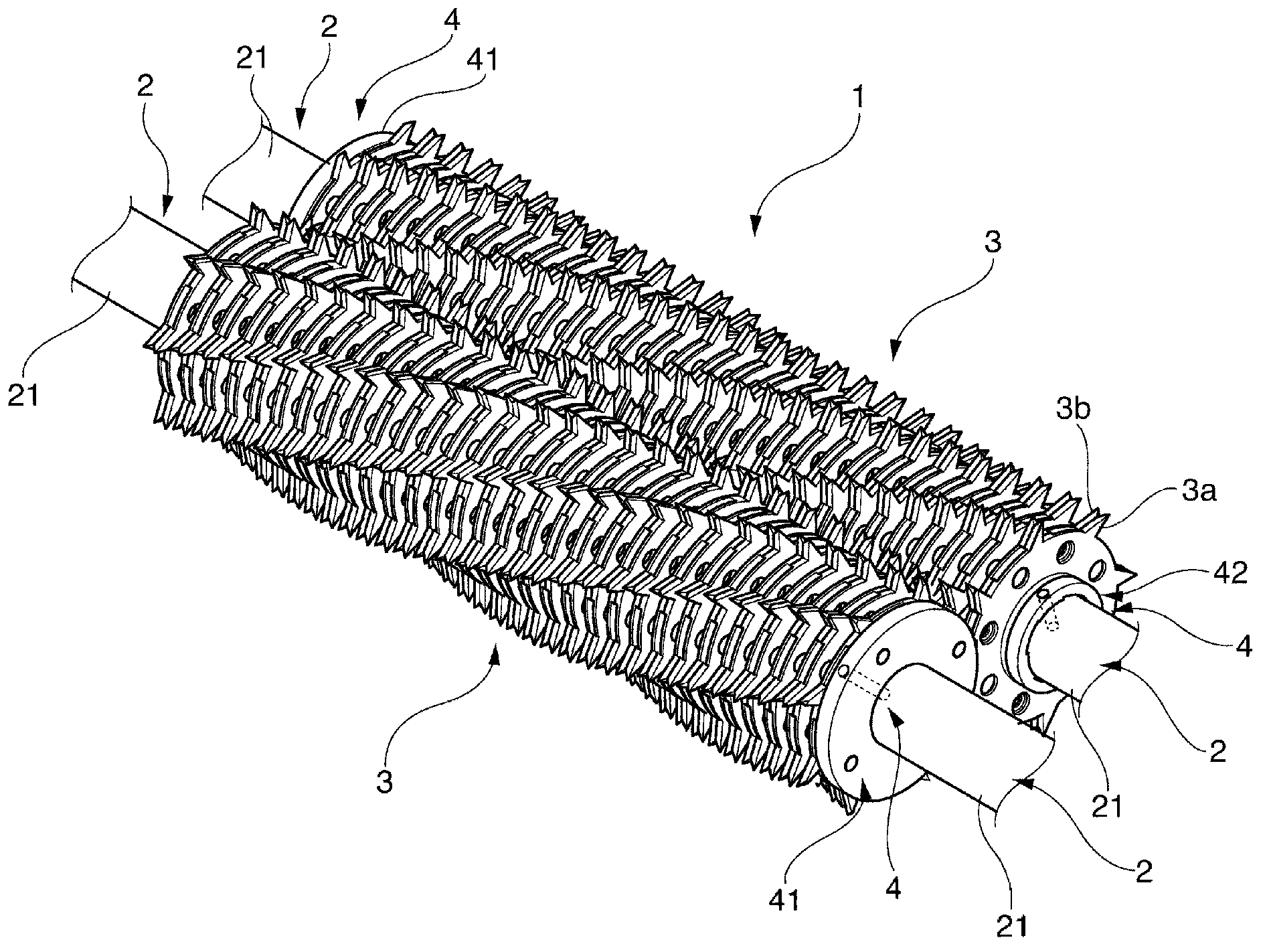
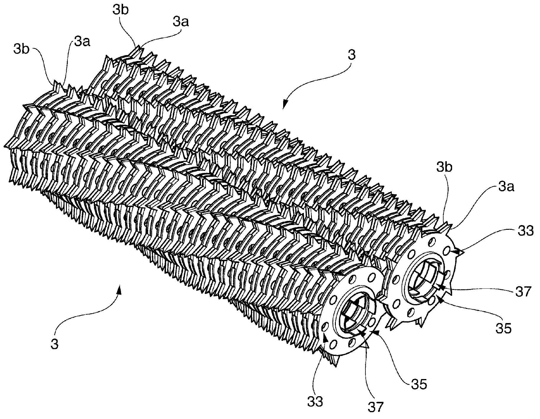
[0098] As shown in the figure, the crushing blade 3 is constituted by at least fitting the inner sides of two paired discs 3a, 3b. Furthermore, these disks 3a and 3b have the following constituent elements as the constituent elements of the crushing blade 3 similarly to the first embodiment described above. That is, the pulverizer blade 3 has a folded portion 31 , a fitting portion 33 , a partition portion 34 , and a shaft insertion hole 37 for inserting the pulverizer blade 3 itself through the rotation shaft. In addition, the same applies to the point that the engaging portion 35 is arranged such that the disk 3 b is offset at a predetermined an...


PUM


Abstract

A cutter having sufficient strength obtained using a reduced amount of a metallic material. A roller cutter (1) for a shredder (S) is provided with: a rotating shaft (2) rotationally driven by a drive mechanism; finely cutting blades (3) each comprising disks (3a, 3b) joined together on the inner sides thereof, the finely cutting blades (3) being installed sequentially on and supported by the rotating shaft (2) with the angular phase of each of the blades (3) displaced a predetermined angle from each other; and shaft affixation members (4) which are, while being mounted to both ends of the finely cutting blades (3), affixed to the rotating shaft (2) to affix the finely cutting blades (3) to the rotating shaft (2). In the roller cutter (1), the finely cutting blades (3) have thick-walled folded sections (31) which are formed by folding inward the metallic sheet material which forms the disks (3a, 3b), and which are in contact with each other.

Description

technical field [0001] The present invention relates to a paper shredder capable of crushing paper and the like, and a paper shredder hob used in the paper shredder. Background technique [0002] The shredder is equipped with a shredding mechanism having a hob capable of shredding paper and / or credit cards, or objects to be shredded such as CDs and / or DVDs. As a structure of this pulverizing mechanism, generally, a structure in which a pair of hobs are arranged in parallel and partially overlap each other is known. When the paper shredder is used, the object to be shredded is inserted between the pair of hobs, and these opposing hobs are rotated in a direction to pull in the object to be shredded. In this way, the object to be crushed is crushed between the paired hobs. Such shredders are divided into: a linear type that discharges strip-shaped shreds by simply shredding the object to be shredded in the insertion direction; The so-called cross type described in Patent Doc...

Claims


Application Information

Patent Timeline
Patent Type & Authority Applications(China)
IPC IPC(8): B02C18/18B02C18/06
CPCB02C18/0007B02C18/182
Inventor 玉置哲朗小池诚一中村慎二吉井达
Owner KOKUYO CO LTD
Learn More