
Chipless passive rfid tag

一种标签、RFID标签的技术,应用在无芯无源射频识别标签领域,能够解决数据存储容量低等问题

Inactive Publication Date: 2013-01-16
INSTITUT NAT POLYTECHN DE GRENOBLE +1
View PDF2 Cites 6 Cited by
  • Summary
  • Abstract
  • Description
  • Claims
  • Application Information

AI Technical Summary

Problems solved by technology

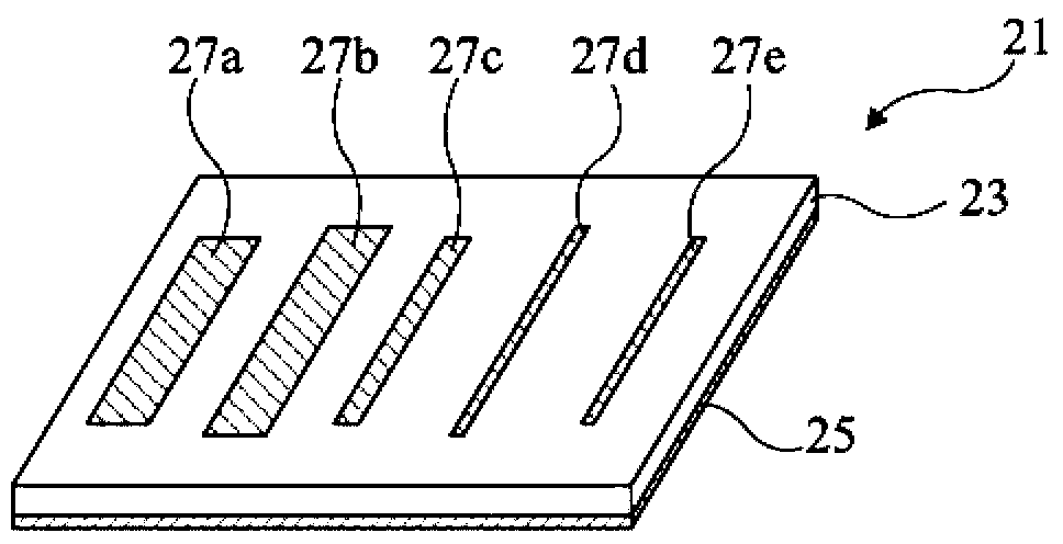
[0013] In addition, refer to figure 2 Coreless tags of the type described have a relatively low data storage capacity per unit surface area

Method used


Image

  • Chipless passive rfid tag
  • Chipless passive rfid tag
  • Chipless passive rfid tag

Examples


Embodiment Construction

[0038] For purposes of clarity, the same reference numbers will be used to designate the same elements in the different drawings, and the various drawings are not drawn to scale.

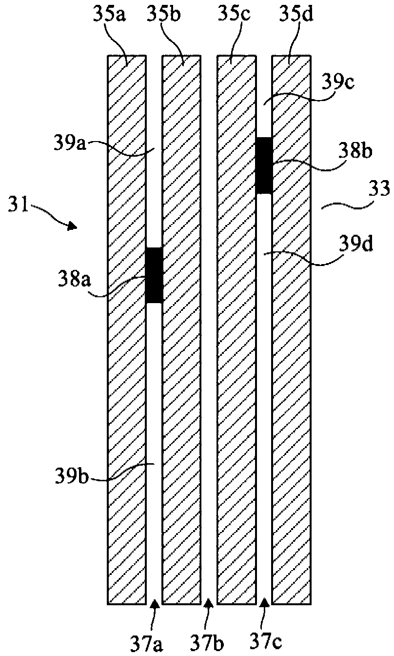
[0039] image 3 It is a top view schematically showing an embodiment of the coreless RFID tag 31 . The label 31 is formed on the dielectric support 33, and the label 31 supports a conductive pattern on one of its two surfaces. On this surface, four separate parallel linear conductive strips 35a to 35d are formed. The conductive strips 35a to 35d are identical, aligned in a direction perpendicular to the conductive strips, and separated from each other by the same distance. Therefore, the conductive strips 35a to 35d define three identical linear dielectric strips 37a to 37c. Conductive bridges interconnect adjacent conductive strips to define portions of different lengths of the dielectric strip between the conductive strips. In this example, the two conductive bridges 38a and 38b connect the ad...


PUM


Abstract

A chipless RFID tag comprises a plurality of disjoint parallel conducting bands formed on a dielectric support, in which conducting bridges interlink neighboring conducting bands, the conducting bridges delimiting, between the conducting bands, portions of dielectric bands of distinct lengths, each portion of dielectric brand determining a resonant frequency of the tag, the set of resonant frequencies of the tag defining an identification code.

Description

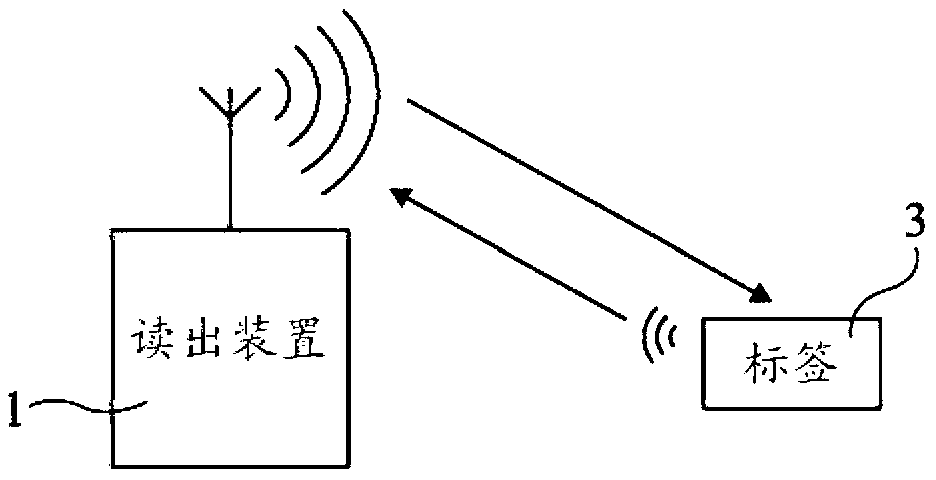
technical field [0001] The invention relates to a tag capable of storing data remotely readable by an adapted reading terminal. More specifically, the present invention is directed to a remote identification technology using electromagnetic waves, now known as RFID (Radio Frequency Identification) in the prior art. Devices operating at frequencies in the range between 10 MHz and 10 THz are more specifically considered herein. Background technique [0002] Currently, data exchange systems in RFID technology are used to recognize and / or identify all types of objects with adapted tags at short or medium distances. [0003] figure 1 A remote identification system in RFID technology is very schematically shown, which system includes a reading terminal 1 and an identification tag (TAG) 3 . The reading terminal 1 comprises in particular an antenna, which is coupled to radio wave transceiver means. The tag 3 contains identification data and, when placed close to the reading term...

Claims


Application Information

Patent Timeline
Patent Type & Authority Applications(China)
IPC IPC(8): G06K19/067G08B13/24
CPCG06K19/0672Y10T29/49016
Inventor 艾蒂安·佩雷斯梅尔·提贾尼德普·瓦苏德万耐尔弗雷德里克·加勒特莱昂内尔·迪维拉雷阿尔诺·莫里斯·维纳
Owner INSTITUT NAT POLYTECHN DE GRENOBLE
Learn More