A system and method for eye imaging

An imaging and eye technology, which is used in eye testing equipment, medical science, diagnosis, etc., can solve the problems of eliminating ghosts and stray light with complex optical structure, unable to completely eliminate ghosts and stray light, and low light source utilization. , to achieve the effect of comfortable inspection, low cost and guaranteed image quality

Active Publication Date: 2014-10-29
SHANGHAI MEDIWORKS PRECISION INSTR CO LTD
View PDF6 Cites 0 Cited by
  • Summary
  • Abstract
  • Description
  • Claims
  • Application Information

AI Technical Summary

Problems solved by technology

[0005] 1. Ghosting and stray light cannot be completely eliminated, and the resulting image quality is still poor
[0006] 2. The illumination light path and observation light path are independent, and the cost is high
[0007] 3. The optical structure for eliminating ghost and stray light is relatively complex and bulky
[0008] 4. When the annular diaphragm is used, the utilization rate of the light source is low, so the energy consumption is relatively large
[0009] 5. The luminous flux entering the patient's eyes is relatively large, which may easily cause eye discomfort for the patient
[0010] At present, there is no imaging system and method that overcomes the above defects, has higher imaging quality, relatively simple structure, low cost, less energy consumption, and less side effects on patients' eyes.

Method used


Image

  • A system and method for eye imaging
  • A system and method for eye imaging
  • A system and method for eye imaging

Examples


Embodiment Construction

[0053] The specific embodiment of the present invention will be further elaborated below in conjunction with accompanying drawing:

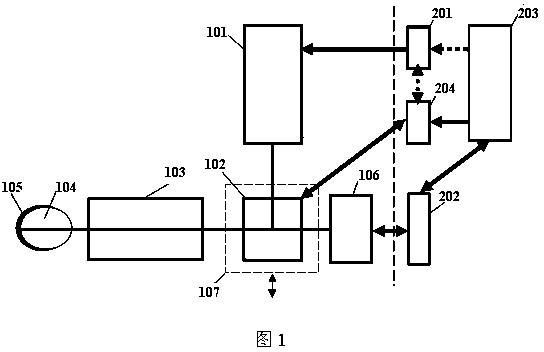
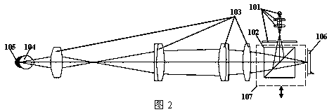
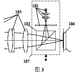
[0054] exist figure 1 In a principle diagram of an embodiment of the present invention, the system includes a light source module 101, a light splitting module 102, a shared optical path module 103, an eye 104, a fundus 105, an image receiver 106; a light source power supply module 201, an image receiver drive module 202, The control processes the display module 203 . A motion optics module 107 and a motion drive module 204 are provided at the same time. In this figure, the motion optics module 107 only includes the light splitting module 102 as a representative to illustrate the facility process. In other words, the motion optics module 107 includes at least the light splitting module 102. Module 102, is a minimal configuration.

[0055] The motion drive module 204 is connected with the motion optics module 107 to directly control the motion o...


PUM


Abstract

The invention discloses an eye imaging system and method which relates to the field of an ophthalmic optical instrument and aims at removing ghosts of shoot during the eye examination to obtain a high-quality image. The device comprises a light source module (101), a light splitting module (102), a common light path module (103), an eye (104), an eye fundus (105), an image receiver (106), a moving optical module (107), an observation diaphragm (108), a light source power supply module (201), an image receiver driving module (202), a control treatment display module (203) and a moving driving module (204). The moving optical module (107) at least comprises the light splitting module (102); the moving driving module (204) is connected with the moving optical module (107) and drives the moving optical module (107), so that illumination lights are reflected to the image receiver (106) to expose after scanning the eye (104) and are spliced and imaged by the control treatment display module (203), and the device and method is mainly used for fundus examination.

Description

technical field [0001] The invention relates to the field of ophthalmic optical instruments, in particular to an eye imaging system and method. Background technique [0002] At present, optical instruments for eye detection or photography generally include an illumination optical path and an observation optical path. The illumination optical path is used to illuminate the eyes of the observed person, and the reflected light is irradiated to the observer's eyes or the observation device through the observation optical path. to observe and photograph the health status of the eyes, including the fundus. [0003] However, due to the complex structure of the patient's eyes, the specific physiological tissue conditions are also varied. Especially when optical instruments are used for observation and photography, in many cases, excess reflected light from the cornea and the eye lens will form ghost images after passing through the optical instruments, thereby reducing In order to ...

Claims


Application Information

Patent Timeline
Patent Type & Authority Patents(China)
IPC IPC(8): A61B3/14
Inventor 严苏峰魏悦陈文光孔昭松
Owner SHANGHAI MEDIWORKS PRECISION INSTR CO LTD
Why Eureka
Try Eureka