Rotor of a hammer crusher

A technology of hammer crusher and rotor, which is applied in the direction of grain processing, etc., to achieve the effect of high performance and high transmission

Inactive Publication Date: 2013-01-23
克劳斯里希特
View PDF10 Cites 15 Cited by
  • Summary
  • Abstract
  • Description
  • Claims
  • Application Information

AI Technical Summary

Problems solved by technology

In the case of pentagonal shafts, a measurement-technical check of the manufacturing accuracy is also only conditionally or only difficultly possible

Method used


Image

  • Rotor of a hammer crusher
  • Rotor of a hammer crusher
  • Rotor of a hammer crusher

Examples


Embodiment Construction

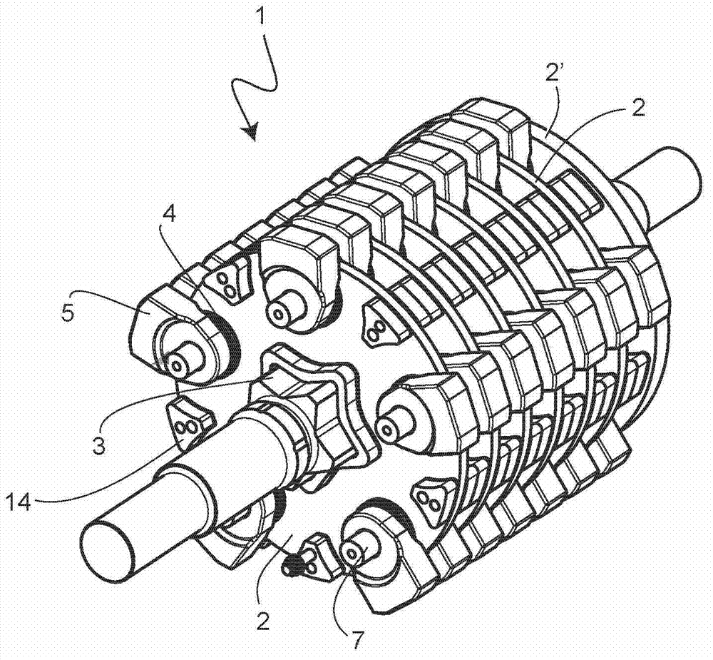
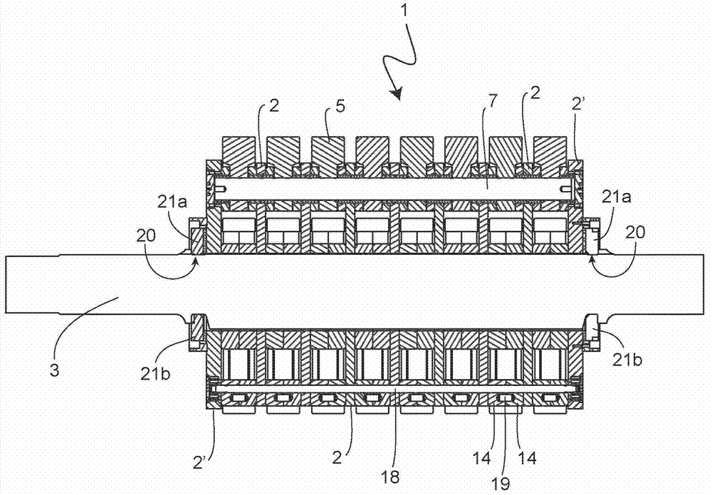
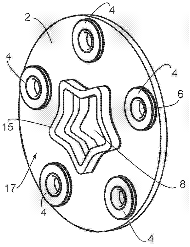
[0028] The rotor of the hammer crusher, marked with reference number 1 in general, is in figure 1 Chinese and Israeli stereograms and in figure 2 Shown in cross-sectional view. The rotor 1 is a part of a single-rotor or multi-rotor hammer crusher or vibratory crusher. The rotor 1 basically has a plurality of circular rotor disks 2 with a small axial width, wherein, for reasons of overview, in figure 1 with figure 2Only three rotor disks 2 are provided with reference numerals. The rotor 1 according to the invention has at least more than two rotor disks 2 . The rotor disks 2 are inserted on the shaft 3 in a rotationally fixed manner. Between two adjacent rotor disks 2 , a plurality of striking hammers 5 are arranged evenly distributed over the circumference of the rotor disks 2 , and are mounted in a freely rotatable manner. as especially in image 3 with Figure 4 It can be seen from the figure that the respective rotor disk 2 has a plurality of through-holes 6 which...


PUM


Abstract

A rotor (1) of a hammer crusher has at least two rotor disks (2) arranged at a distance from each other on a shaft (3, 3') in a torque-proof manner. Percussion hammers (5) are pivotably supported in a radial distance to the shaft (3, 3') between the adjacent rotor disks (2). A solution has to be provided for improving the torque transmission between the shaft and the rotor disks in a simple and low-cost manner and enabling the rotor to have persistent good utilization characteristics during a very long service life. The solution is that: the shaft (3, 3') is formed as star-shaped in cross-section with tips (9, 9'), where one tip (9, 9') is defined by two radially outwardly running side surfaces (10, 11, 10', 11').

Description

technical field [0001] The invention relates to a rotor for a hammer crusher with at least two rotor disks which are fixedly arranged on a shaft at a distance from one another, wherein a plurality of impact hammers are arranged radially at a distance from the shaft It is pivotally supported between two adjacent rotor disks. Background technique [0002] Hammer crushers with such rotors are used for crushing a wide variety of materials and with a high degree of crushing. In this case, the hammer crusher with one or two rotors is embodied as a single-shaft or double-shaft hammer crusher. The rotor of a hammer crusher is known, for example, from DE 27 13 177 C2 and comprises a shaft and a number of circular rotor disks attached to the shaft at a lateral distance from each other, between which five impact hammers can Arranged in rotational motion on the periphery. The shaft has a circular cross section, so that the extension of the hammer beyond the height, that is to say the...

Claims


Application Information

Patent Timeline
Patent Type & Authority Applications(China)
IPC IPC(8): B02C13/28
CPCB02C2013/2808B02C13/26B02C13/04
Inventor 克劳斯·里希特托马斯·伍斯特曼
Owner 克劳斯里希特
Why Eureka
Try Eureka