
Three-dimensional printing line light condensing source adopting solar energy and printing method

A printing line, solar energy technology, applied in optics, optical components, instruments, etc., can solve the problem of high cost of laser energy, achieve the effect of small effective reflection area, small rotation, and cost reduction

Inactive Publication Date: 2013-01-23
张德胜
View PDF3 Cites 5 Cited by
  • Summary
  • Abstract
  • Description
  • Claims
  • Application Information

AI Technical Summary

Problems solved by technology

[0008] In order to overcome the disadvantage of high cost of using laser energy in rapid prototyping technology, the present invention provides a three-dimensional printing line concentrating light source using solar energy, which can use solar energy instead of fossil fuels in the process of selective sintering of granular materials Energy-driven; it can use solar energy for a longer time, and the way of concentrating light is more reasonable

Method used


Image

  • Three-dimensional printing line light condensing source adopting solar energy and printing method
  • Three-dimensional printing line light condensing source adopting solar energy and printing method
  • Three-dimensional printing line light condensing source adopting solar energy and printing method

Examples


Embodiment Construction

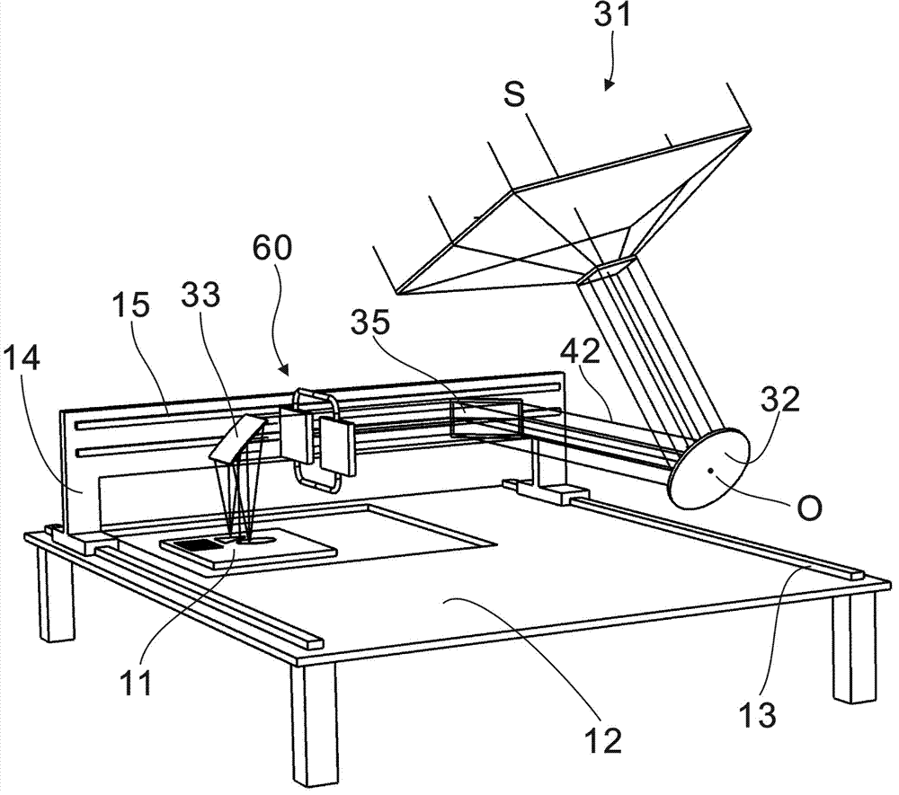
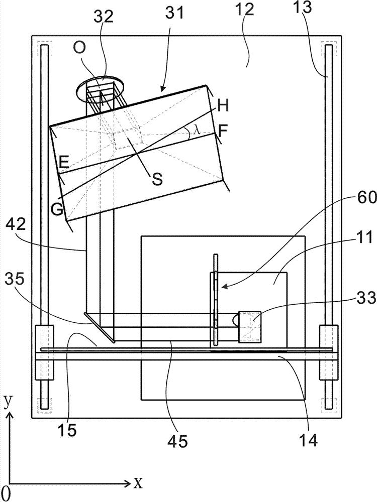
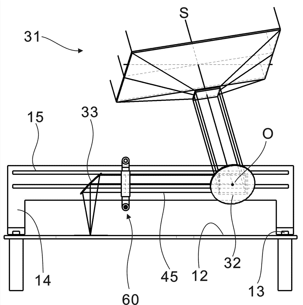
[0033] As shown in Fig. 1, Fig. 2, Fig. 3 and Fig. 4, the present invention provides a three-dimensional printing line concentrating light source utilizing solar energy, including: a sintering surface 11, a working platform 12, a meridian linear track 13, and a meridian translation support 14. Latitude linear track 15, concentrator 31, horizontal meridian mirror 32, horizontal latitude mirror 35, parabolic mirror 33, light shield 60; sintering surface 11 is composed of materials with smaller particles Horizontal plane; the upper surface of the working platform 12 is a horizontal plane, and the meridian linear track 13 is fixed on the upper surface of the working platform 12, facing the north-south direction; the meridian translation support 14 is installed on the meridian linear track 13, and can move horizontally along the north-south direction; The latitudinal linear track 15 and the horizontal latitudinal reflector 35 are fixedly installed on the warp-direction translation s...


PUM


Abstract

The invention provides a three-dimensional printing line light condensing source adopting solar energy and a printing method. The three-dimensional printing line light condensing source adopting solar energy comprises a sintering face, a working table, a longitudinal linear rail, a longitudinal translation support, a latitudinal linear rail, a light condenser, a horizontal longitudinal reflector, a horizontal latitudinal reflector, a parabolic cylinder reflector and a light chopper; the parallel condensing light output by the light condenser passes through the horizontal longitudinal reflector, the horizontal latitudinal reflector, the light chopper and the parabolic cylinder reflector, so as to form light condensing lines on the surface of the sintering face; the light chopper comprises a transparent container, a heat-conducting medium, a light chopping grating and a radiator; the light chopping grating comprises a plurality of strip shaped gratings; the electrochromism voltage of each strip shaped grating is controlled, thus, dot matrixes with light different condensing energies can be obtained from the light condensing lines, and granular materials can be selectively sintered through the solar condensing energy. With the adoption of the three-dimensional printing line light condensing source adopting solar energy provided by the invention, the time for utilizing the solar energy is prolonged, the most reasonable way is provided for condensing and utilizing the light, and the shortcoming that high cost is needed for utilizing the laser energy in rapid prototyping manufacturing technology is overcome.

Description

technical field [0001] The invention relates to the technical fields of solar energy utilization technology and rapid prototyping (RPM), in particular to a light source and a printing method for selectively sintering and printing granular materials by utilizing the concentrated energy of solar energy and the principle of electrochromism. Background technique [0002] In the current field of industrial design and manufacturing, rapid prototyping refers to the general term for related technologies that directly drive the forming equipment from the digital model of the product to rapidly manufacture any three-dimensional physical entity. It establishes a three-dimensional digital model of the product in the computer through forward design or reverse mapping, and discretizes the model into a series of ordered units according to specific requirements; usually, it is discretely layered according to a certain thickness in the Z direction. The original 3D model becomes a series of 2...

Claims


Application Information

Patent Timeline
IPC IPC(8): B29C67/04B22F3/10G02B26/10
Inventor 张德胜
Owner 张德胜
Learn More