
Acoustic logging transmitting transducer driving system

A technology for transmitting transducers and driving systems, which is used in surveying, wellbore/well components, earth-moving drilling, etc. It can solve the problem that users cannot control the frequency of sound sources, and achieve the effect of improving the applicability of the formation and reducing the frequency.

Inactive Publication Date: 2013-01-23
THE 22ND RES INST OF CHINA ELECTRONICS TECH GROUP CORP
View PDF5 Cites 7 Cited by
  • Summary
  • Abstract
  • Description
  • Claims
  • Application Information

AI Technical Summary

Problems solved by technology

At present, the transmitting transducer of the acoustic logging tool is usually excited by a high-voltage rectangular pulse of a certain width, and the user cannot control the frequency of the sound source according to the needs of engineering or scientific research.

Method used


Image

  • Acoustic logging transmitting transducer driving system
  • Acoustic logging transmitting transducer driving system
  • Acoustic logging transmitting transducer driving system

Examples


Embodiment 1

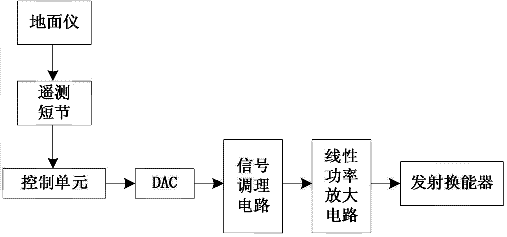
[0015] Embodiment 1: as figure 1 The driving system of the acoustic logging transmitting transducer shown is mainly composed of a surface waveform design module, a waveform generating module, a power amplification module and a transmitting transducer. It is used to drive the transmitting transducer of the acoustic logging tool. The purpose is to radiate sound waves to the formation by controlling the excitation of the transmitting transducer. More specifically, it is used to control the sound source characteristics (frequency band, amplitude, etc.) of the acoustic logging tool. control. Among them, the driving method of the transmitting transducer is suitable for the excitation of the transmitting transducers of various acoustic logging tools such as monopole, dipole, and quadrupole, and is suitable for piezoelectric transducers and electromagnetic transducers of various shapes and structures. Devices (etc.) are adaptable.

[0016] figure 1 The functions of each part are de...


PUM


Abstract

The invention relates to an acoustic logging transmitting transducer driving system, which comprises a ground waveform design module, a waveform generation module, a power amplification module and a transmitting transducer. A user selects or designs waveform data with different frequency bands or a control instruction according to the needs by using a ground instrument and transmits the data or construction to an underground control unit of an acoustic logging instrument through telemetry cartridge; and the underground control unit controls a digital / analog (D / A) converter to generate low-voltage analog waveform, performs signal conditioning through a filtering circuit and an amplification circuit, outputs Signal waveform, performs power amplification on the Signal waveform by utilizing a power amplification circuit and finally applies the Signal waveform to the transmitting transducer so as to radiate acoustic waves outwards. The acoustic logging transmitting transducer driving system has the advantages that the impulse waveform of a transmitting circuit can be designed on the ground, more favorable excitation waveforms are selected according to the geological conditions and logging needs, and better logging data is acquired; and moreover, the formation applicability of an acoustic logging instrument is improved.

Description

technical field [0001] The invention relates to the technical field of acoustic logging, in particular to a driving system for an acoustic logging transmitting transducer. Background technique [0002] Acoustic logging is one of the main methods of geophysical logging, and it is widely used in the exploration and development stages of oil and gas fields. Theoretical and experimental studies have shown that the frequency band characteristics of the sound source have a great influence on the logging effect, and an appropriate sound source frequency band should be used for different logging purposes and geological conditions. For example: for monopole acoustic logging, a higher sound source frequency is usually required to highlight the longitudinal and transverse waves; and to obtain better Stoneley waves, it is necessary to work in low frequency mode; for cased hole cementing quality logging Generally speaking, the main frequency of the sound source is usually set at about 2...

Claims


Application Information

Patent Timeline
IPC IPC(8): E21B47/14E21B49/00
Inventor 张博王军杰王武营成思周祥熹邓方青刘峰常平平殷谦乔喜梅
Owner THE 22ND RES INST OF CHINA ELECTRONICS TECH GROUP CORP
Learn More