
Gas electromagnetic radiation thermal energy wave directional cluster reflection device

A technology of electromagnetic radiation and reflection device, applied in the direction of household heating, household heating, heating method, etc., can solve the problem of not being able to reflect heat energy, and achieve the effect of reducing heat transfer loss, increasing radiation angle, and reducing loss.

Active Publication Date: 2016-03-02
梁广海 +1
View PDF8 Cites 0 Cited by
  • Summary
  • Abstract
  • Description
  • Claims
  • Application Information

AI Technical Summary

Problems solved by technology

[0002] Gas electromagnetic wave radiation heat energy, as a heating technology, is increasingly adopted on a large scale. The existing technology only reflects the light source to the object to be heated through the reflection device, but it cannot reflect the heat energy with maximum efficiency.
There is a large amount of loss in the process of heat energy reflection, which is a problem that has plagued the field of gas electromagnetic wave heat energy for many years with serious heating heat loss

Method used


Image

  • Gas electromagnetic radiation thermal energy wave directional cluster reflection device
  • Gas electromagnetic radiation thermal energy wave directional cluster reflection device

Examples


Embodiment Construction

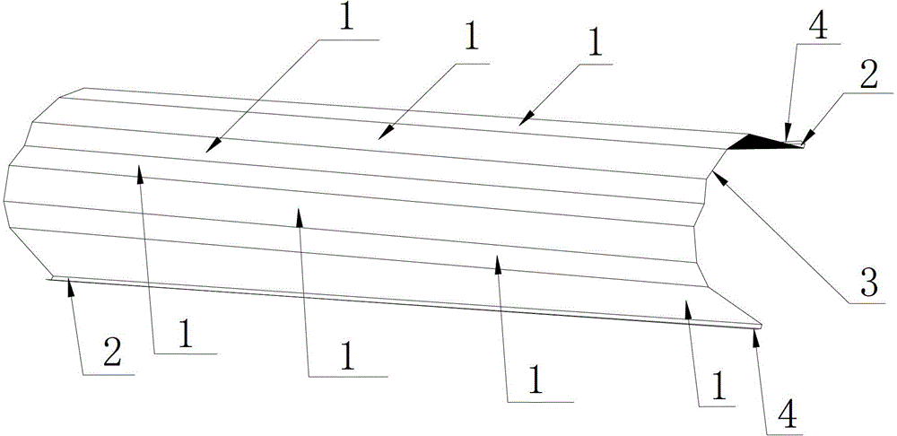
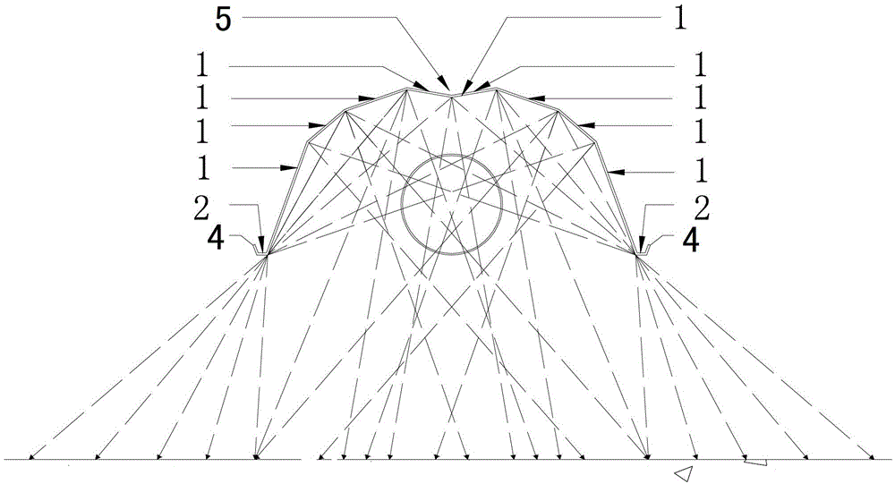
[0017] Such as figure 1 As shown, a gas electromagnetic radiation thermal energy wave directional bundle reflection device described in the embodiment of the present invention includes eight reflectors 1 and two rigid flanges 2, and the two rigid flanges 2 pass through sequentially The eight reflecting plates 1 connected to each other are connected; the bottom surface of the reflecting plate 1 is provided with a reflecting surface 3, and the outer side of the rigid flange plate 2 is provided with a flanging 4; the eight reflecting plates 1 are symmetrically arranged on two rigid Between the flange plates 2 , the overall section of the eight sequentially connected reflectors 1 is arc-shaped, and the two reflectors 1 at the top of the arc form grooves 5 inward. From left to right, the angles between every two adjacent reflecting plates 1 are 151°, 158°, 151°, 161°, 151°, 158°, 151° respectively.

[0018] The length of the rigid flange plate 2 is 2400mm, the width is 348mm, and ...


PUM


Abstract

The invention relates to a fuel gas electromagnetic radiation heat energy wave oriented concentration beam reflective device which comprises a plurality of reflecting plates and two rigid flanged plates, wherein the rigid flanged plates are connected through a plurality of reflecting plates which are successively connected, the bottom surfaces of the reflecting plates are provided with reflecting surfaces, and outer sides of the rigid flanged plates are provided with flangings; the quantity of the reflecting plates is eight, and the eight reflecting plates are symmetrically arranged between the two rigid flanged plates; and the whole sections of the eight reflecting plates which are successively connected are arc shapes, and two reflecting plates positioned on the top ends of the arc shapes inward form a groove. The fuel gas electromagnetic radiation heat energy wave oriented concentration beam reflective device provided by the invention has the beneficial effects that the reflective device can uniformly reflect heat energy wave in a centralization manner, the heat energy wave is directionally sent to a heated object, the heat transmission loss is reduced, and the heat efficiency is high, and the reflective device is high efficiency, energy-saving, uniform, comfort, safe and reliable; and compared with a reflex cover with a single reflection surface, the heat energy wave is repeatedly stacked to carry out reflection and refraction, a radiation angle is increased, the radiating area is amplified, and meanwhile, the heating comfortability is improved.

Description

technical field [0001] The invention relates to a gas electromagnetic radiation thermal energy wave directional bundle reflection device. Background technique [0002] Gas electromagnetic wave radiation heat energy, as a heating technology, is increasingly adopted on a large scale. The existing technology only reflects the light source to the object to be heated through a reflecting device, but cannot reflect heat energy with maximum efficiency. There is a large amount of loss in the process of heat energy reflection, which is a problem that has plagued the field of gas electromagnetic wave heat energy for many years with serious heating heat loss. Contents of the invention [0003] The purpose of the present invention is to provide a gas electromagnetic radiation thermal energy wave directional bundle reflection device, which makes the thermal energy wave repeatedly superimposed reflection and refraction, increases the radiation angle, and increases the radiation area, so...

Claims


Application Information

Patent Timeline
Patent Type & Authority Patents(China)
IPC IPC(8): F24D19/06
Inventor 梁广海梁广彬
Owner 梁广海
Learn More