Assembled structure of brake release knob

A button and structure technology, which is applied in the field of brake release button assembly structure, can solve the problems of button breakage, difficulty in confirming the brake release button, and failure to obtain the specified installation force

Inactive Publication Date: 2013-01-30
HONDA MOTOR CO LTD +1
View PDF6 Cites 2 Cited by
  • Summary
  • Abstract
  • Description
  • Claims
  • Application Information

AI Technical Summary

Problems solved by technology

[0007] However, in such a conventional technique, there is a problem caused by variation in the installation allowance of the interference fit.
That is, when the mounting margin is small, the predetermined mounting force may not be obtained. On the other hand, if the mounting margin

Method used


Image

  • Assembled structure of brake release knob
  • Assembled structure of brake release knob
  • Assembled structure of brake release knob

Examples


Example Embodiment

[0032] Hereinafter, a preferred embodiment of the present invention will be described based on the drawings.

[0033] Each figure shows an embodiment of the present invention.
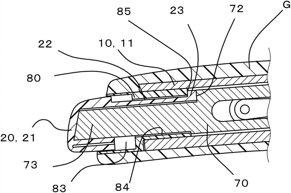
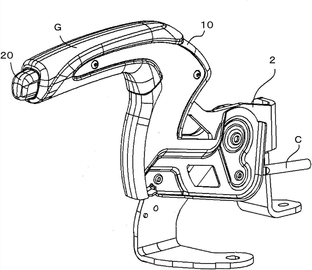
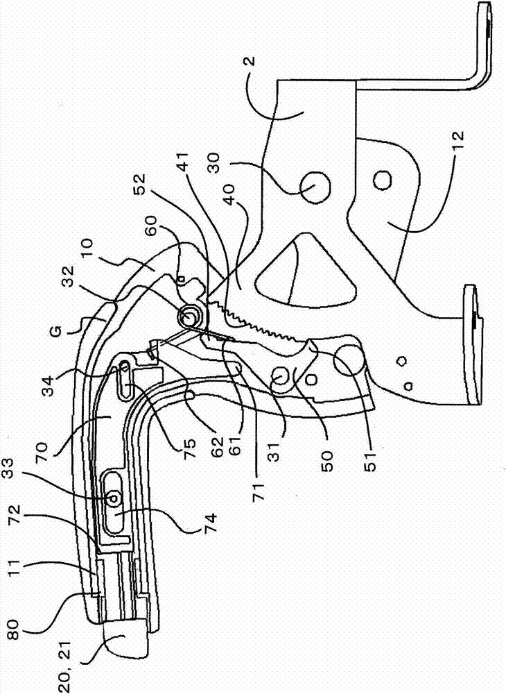
[0034] Such as Figure 1 to 3 As shown, with regard to the parking brake 1 of the present invention, the brake lever 10 is pivotally supported on the base member 2 fixed on the side of the vehicle body in a manner that can be pulled up and down. The movable lever 10 transmits force to the brake portion via a cable not shown to generate a braking force. When the brake is released from the braking state, the brake release button 20 disposed on the side of the front end portion 11 of the brake lever is pressed. Put it into the brake lever 10 and tilt the brake lever 10 down. For the brake lever 10, in order to improve the usability during operation, the handle G is used to cover the part held by the hand during operation.

[0035] The base end portion 12 of the brake lever 10 on the side opposite to the brake ...


PUM


Abstract

An assembled structure of brake release knob that assures a predetermined anchoring force, and reliable anchoring with no damage being caused in assembling. A cap (80) is fixed in a brake lever distal end part (11); a brake release knob (20) is inserted into the cap (80); a flange part (23) formed on a leg part (22) extending from a head part (21) of the brake release knob is engaged with an innermost end (85) of the cap; in the brake lever distal end part (11), a distal end part taperedly extending from a shoulder part (72) of a release rod (70) is inserted closer to the center of the cap (80) than the leg part (22) of the brake release knob; and between the shoulder part (72) and the innermost end (85) of the cap, the flange part (23) of the brake release knob is sandwiched under pressure.

Description

technical field [0001] The present invention relates to an assembly structure of a brake release button of a parking brake in which a brake lever is pivotally supported on a base member in a pull-up and fall-down manner, and when the brake lever is pulled up, the brake lever is pulled up and moved to the parking brake via a cable. The brake part transmits force to generate braking force. When the brake is released from the braking state, the brake release button, which is arranged on the front end of the brake lever and receives force from the release lever side, is pushed in against the force. Put down the brake lever mentioned above. Background technique [0002] As a conventional parking brake of this type, there is a device described in Patent Document 1, for example. [0003] In such a lever-type parking brake, a brake release button for releasing the braking state of the brake is attached using a concave-convex pin provided at the front end of a resin release lever or...

Claims


Application Information

Patent Timeline
IPC IPC(8): B60T7/10
CPCB60T7/105B60T7/10Y10T74/20612Y10T74/20648Y10T74/20696
Inventor 河野英治增田觉
Owner HONDA MOTOR CO LTD
Why Eureka
Try Eureka