Optical axis stable platform

A technology for stabilizing the platform and optical axis, which is applied in transportation, packaging, aircraft parts, etc., can solve the problems of high cost, low precision and high precision, and achieve the effect of low cost, high precision and high processing precision

Inactive Publication Date: 2017-09-19
CHONGQING UNIV
View PDF4 Cites 1 Cited by
  • Summary
  • Abstract
  • Description
  • Claims
  • Application Information

AI Technical Summary

Problems solved by technology

[0004] The purpose of the present invention is to propose a device that utilizes piezoelectric ceramic actuators to realize optical axis stabilization, which overcomes the shortcomings of the existing optical axis stabilization platform, such as high precision, high cost, low cost and low precision, and has the advantages of low cost, Simple structure, good controllability, high precision, etc.

Method used


Image

  • Optical axis stable platform
  • Optical axis stable platform
  • Optical axis stable platform

Examples


Embodiment Construction

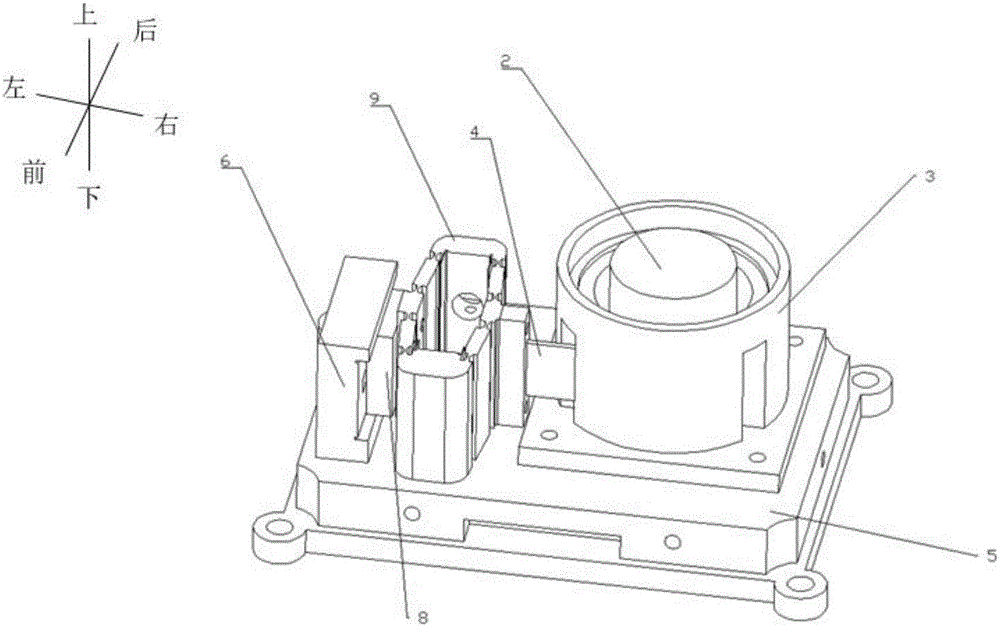
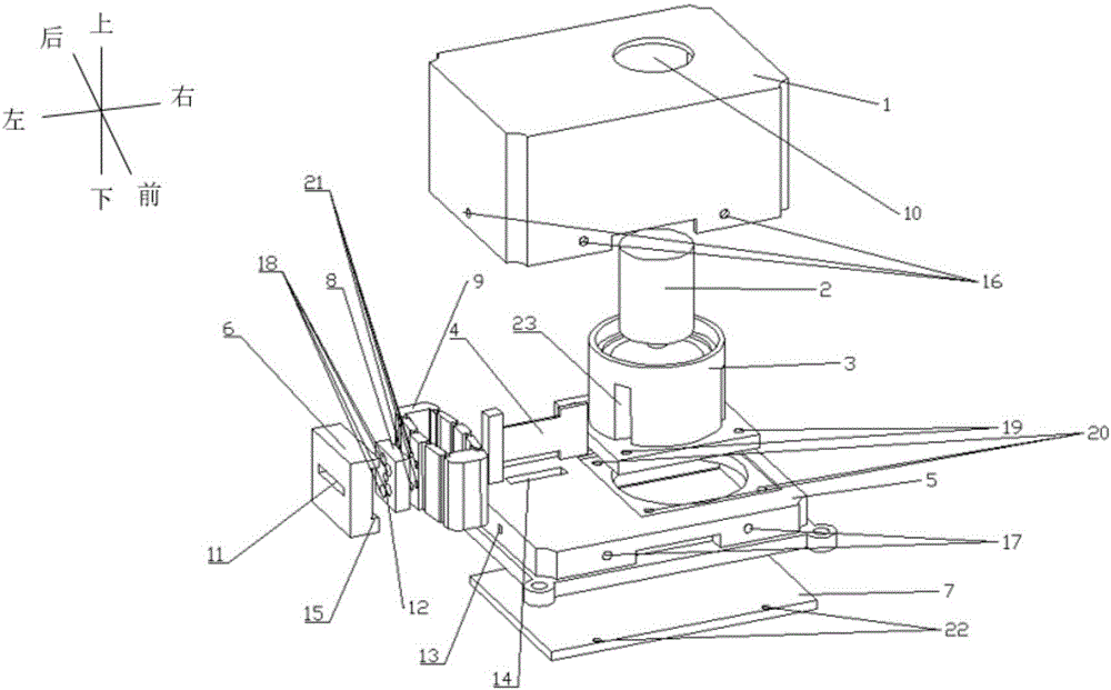
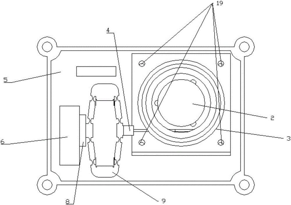
[0026] The present invention will be further described below in conjunction with accompanying drawing.

[0027] Such as Figure 1-Figure 4 The optical axis stabilization platform shown includes the upper part 1 of the housing, the lower part 7 of the housing, the bottom plate 5, the support seat 6 integrated with the bottom plate, the rotating shaft frame 3, the stepped rotating shaft 2, the elastic frame 9 and the push rod 4 integrated with the elastic frame . The upper part of the housing 1 realizes the fixed connection of the two through the screw holes 16 on its side and the screw holes 17 on the side of the bottom plate 5; As a preference, an electronic compartment 25 for placing circuit modules is reserved between the lower part 7 of the casing and the bottom plate 5 . The rotating shaft frame 3 realizes the fixing of the rotating shaft frame 3 through the screw holes 19 evenly distributed in the upper corners of the bottom base and the evenly distributed screw holes 2...


PUM


Abstract

The invention relates to an optical axis stable platform. The optical axis stable platform comprises a base plate, a supporting seat, an elastic frame, a pushing rod, a stepped rotary shaft, a rotary shaft frame and an outer shell. The supporting seat and the base plate are designed into a whole, and a connecting block is arranged between the elastic frame and the supporting seat; the connecting block is connected with the supporting seat through a through groove in the front-back direction, and the other end of the connecting block is connected with the elastic frame through a screw hole; one end of the pushing rod is fixedly connected with the elastic frame, and the other end of the pushing rod is tightly close to the rotary shaft by penetrating through a gap of the rotary shaft frame; and the rotary shaft frame and a rotary shaft seat are designed into a whole and are fixedly connected with the base plate through screw holes. The lower end of the stepped rotary shaft is matched with the bottom end of the rotary shaft frame through bearings, and the upper end of the stepped rotary shaft is matched with the rotary shaft frame through bearings as well; the outer shell is divided into an upper part and a lower part, the upper half part is fixed to a side wing of the base plate through bolts, and the lower half part is fixed to the bottom face of the base plate through bolts; and an electronic cabin is formed between the lower half part of the outer shell and the base plate. The optical axis stable platform has the advantages of being low in cost, simple is structure, good in controllability, high in precision and the like.

Description

technical field [0001] The invention relates to a platform for stabilizing an optical axis, in particular to a platform for realizing optical axis stabilization by using a piezoelectric ceramic actuator and a friction transmission principle. Background technique [0002] The optical axis stabilization platform is a device that isolates the influence of the aircraft's attitude change and mechanical vibration on the pointing of the photoelectric sensor. It is more and more widely used in the fields of UAV technology, aerial surveying and mapping, and aerial photography. With the continuous improvement of the dynamic performance and precision of camera devices and surveying and mapping equipment, the requirements for the optical axis stabilization platform are also continuously increasing, requiring the optical axis stabilization platform to have a simpler structure, better controllability, and higher precision. The existing optical axis stabilization methods include passive vi...

Claims


Application Information

Patent Timeline
Patent Type & Authority Applications(China)
IPC IPC(8): B64D47/08B64D47/00
CPCB64D47/00B64D47/08
Inventor 戴敏鹏刘豪袁刚
Owner CHONGQING UNIV
Why Eureka
Try Eureka