Bar material conveying device

A conveying device and bar technology, which is used in conveyors, conveyor objects, transportation and packaging, etc., can solve the problems of lack of grabbing space for bars, affecting the grasping and grabbing accuracy of robotic arms, and easy to slip.

Active Publication Date: 2013-01-30
TATUNG GEAR KUNSHAN
View PDF7 Cites 31 Cited by
  • Summary
  • Abstract
  • Description
  • Claims
  • Application Information

AI Technical Summary

Problems solved by technology

At present, a horizontal conveyor is usually used, including a conveying group composed of a drive assembly and a belt traction assembly. The bar as a whole is directly in contact with the belt traction ...

Method used


Image

  • Bar material conveying device
  • Bar material conveying device
  • Bar material conveying device

Examples


Embodiment 1

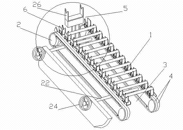
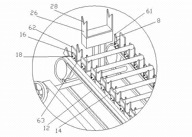
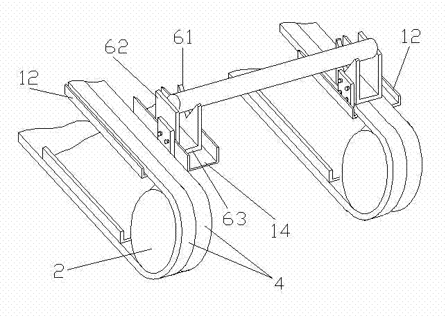
[0020] Embodiment 1: as Figure 1-3 As shown, a bar conveying device of the present invention includes a horizontal conveyor containing two conveying groups with the same conveying direction, a distance adjusting device for adjusting the horizontal distance between the two conveying groups, and a conveying outlet located at the two conveying groups end vertical lifting device. The transmission group is composed of a drive assembly 2 and an endless belt traction assembly, wherein the belt traction assembly is composed of two parallel endless chains 4, and the drive assembly 2 is a gear. Each belt traction assembly is provided with a row of bar seats 6 along the conveying direction. Two rows of bar seats 6 are arranged in parallel, the number of bar seats 6 in each row is equal to the number of bar seats 6 in the other row, and they correspond one by one; the corresponding two bar seats 6 form a group, and The positions in the directions are the same, and the heights relative ...

Embodiment 2

[0022] Embodiment 2: Another bar conveying device (not shown) of the present invention differs from Embodiment 1 only in that it includes two horizontal conveyors arranged in parallel in the conveying direction, and the corresponding two horizontal conveyors respectively lifting device. Moreover, the screw mandrel 22 in the distance adjusting device connects the four conveying groups, and can adjust the distance between the respective conveying groups in the two conveyors. Working with the bar conveying device in Embodiment 2 is equivalent to doubling the conveying capacity, and the two horizontal conveyors work at the same time, which greatly improves the working efficiency.


PUM


Abstract

The invention relates to a bar material conveying device which comprises a horizontal conveying machine. The horizontal conveying machine comprises at least one conveying set formed from a driving assembly and a band type dragging assembly, wherein as least one row of bar bases in the direction of conveying are arranged on the band type dragging assembly, the bar bases comprise supporting plates perpendicular to the annular surface of the band type dragging assembly, and the outer ends of the supporting plates are provided with concave type supporting parts sunk in the direction of the band type dragging assembly. The bar material conveying device provided by the invention is provided with multiple bar bases used for bearing bars, the concave type supporting parts are arranged on the bar bases, so that the positions of the bars in the direction of conveying are stabilized, a certain space is also left below the bars to be conveniently captured by mechanical arms, and the capture accuracy is increased by stabilizing the positions of the bars at the same time.

Description

technical field [0001] The invention relates to a bar conveying device, in particular to a bar conveying device working with a mechanical arm. Background technique [0002] In the field of mechanical processing, the traditional method of transporting the bar to be processed to the processing area by manual feeding is too inefficient. With the advancement of technology, the feeding of the bar is completed by the conveying device, and the conveying device and the processing area are equipped with mechanical arms to complete the grabbing and transferring of the bar. The setting of the conveying device not only greatly improves the conveying efficiency, but also better cooperates with the mechanical arm to improve the grasping efficiency of the mechanical arm. At present, a horizontal conveyor is usually used, including a conveying group composed of a drive assembly and a belt traction assembly. The bar as a whole is directly in contact with the belt traction assembly. Ther...

Claims


Application Information

Patent Timeline
IPC IPC(8): B65G17/12B65G17/36B65G47/34
Inventor 赖国祥
Owner TATUNG GEAR KUNSHAN
Why Eureka
Try Eureka