Shaft end motor of automobile electric control hydraulic independent shaft end driving system

A driving system and electronic control technology, applied in variable displacement engines, machine/engines, reciprocating piston engines, etc., can solve the problems of easy sideslip, low hydraulic motor speed, large space, etc., and achieve stable speed regulation, The effect of torque balance and high transmission efficiency

Active Publication Date: 2013-01-30
吴亚利
View PDF7 Cites 1 Cited by
  • Summary
  • Abstract
  • Description
  • Claims
  • Application Information

AI Technical Summary

Problems solved by technology

[0002] At present, the vehicle drive system usually uses the internal combustion engine to transmit power to the wheels through the gearbox and the transfer device, but the traditional transfer device is prone to sideslip when turning or passing through complex road sections. In addition, the space required for turning is relatively small. Large; the driving force of the wheels cannot be controlled individually; the hydraulic motor speed of the prior art is low

Method used


Image

  • Shaft end motor of automobile electric control hydraulic independent shaft end driving system
  • Shaft end motor of automobile electric control hydraulic independent shaft end driving system
  • Shaft end motor of automobile electric control hydraulic independent shaft end driving system

Examples


Embodiment Construction

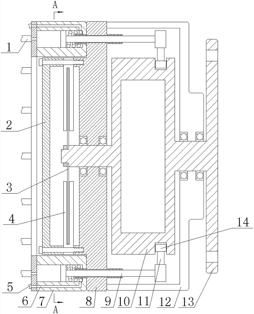
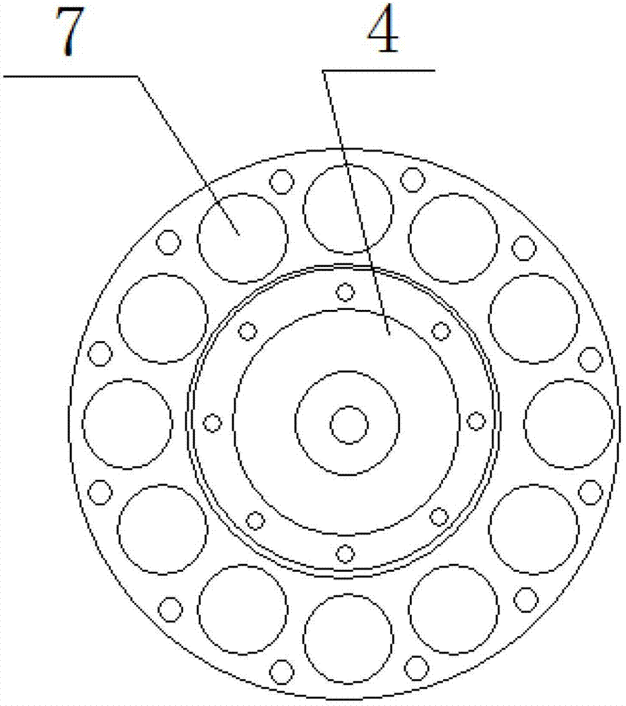
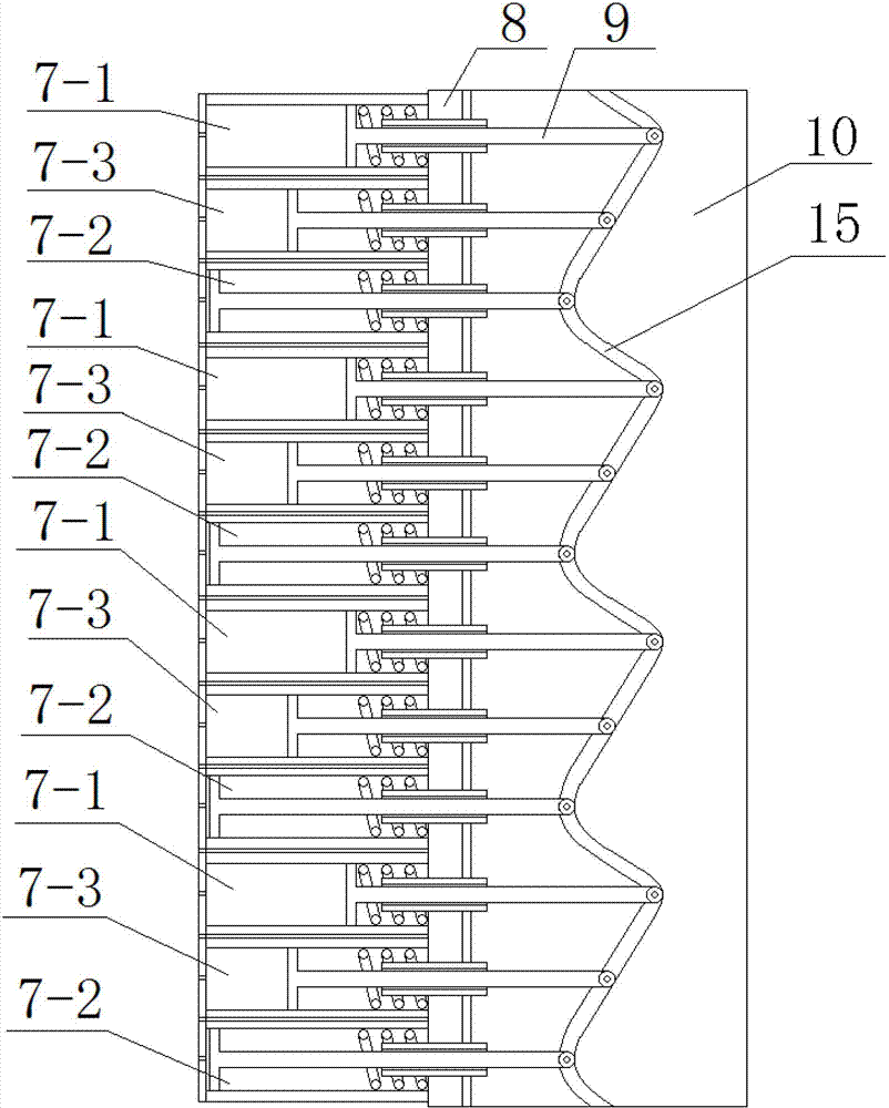
[0013] Such as figure 1 and figure 2 As shown in the figure, the axle-end motor of the automobile electronically controlled hydraulic independent axle-end drive system includes a hydraulic cylinder 7, a main engine, a code disc 3 and a sensor frame 4; its characteristic is that several hydraulic cylinders 7 are perpendicular to and fixed to the inner end cover On the inner end cover 8, and arranged in a circular shape, the end of each hydraulic cylinder piston rod 9 is connected with a push rod 11 perpendicular to the wheel axis, one end of the push rod is fixedly connected to the end of the piston rod, and the other end Connect with slide block 14 through bearing; Described main engine comprises rotor 10 and housing 12, and wherein rotor is cylindrical, as image 3 As shown, a wavy groove 15 is provided on the side of the cylinder; a corresponding number of push rod guide grooves are set on the inner wall of the housing; the slider moves in the wavy groove; as figure 1 As ...


PUM


Abstract

The invention provides a shaft end motor of an automobile electric control hydraulic independent shaft end driving system, aiming at solving the problems that the rotating speed and the output torque of a hydraulic motor are coordinated and matched and intelligently controlled by computer chips. The shaft end motor comprises a hydraulic oil cylinder, a host computer, an encoding disc and a sensor rest. The shaft end motor is mainly characterized in that a plurality of piston connecting rods and slide blocks of the hydraulic oil cylinder move around a rotor in a coordination manner; the straight reciprocating motion of the piston connecting rods and the slide blocks is converted into the circular motion through wave-shaped grooves arranged at the side plane of the rotor; the hydraulic oil cylinder is divided into A-phase, B-phase and C-phase which are arranged circularly; and the encoding disc connected with the rotor shaft end together and the sensor on the sensor rest transmit the position and the operation state information of the rotor to the computer chips to implement intelligent control.

Description

technical field [0001] The invention belongs to the technical field of automobile drive systems, and in particular relates to an axle end motor of an automobile electronically controlled hydraulic independent axle end drive system. Background technique [0002] At present, the vehicle drive system usually uses the internal combustion engine to transmit power to the wheels through the gearbox and the transfer device, but the traditional transfer device is prone to sideslip when turning or passing through complex road sections. In addition, the space required for turning is relatively small. The driving force of the wheels cannot be controlled separately; the hydraulic motor speed of the prior art is relatively low. Contents of the invention [0003] The purpose of the present invention is to solve the problems existing in the prior art, and to provide an axle end motor of an automobile electronically controlled hydraulic independent axle end drive system that can be indepen...

Claims


Application Information

Patent Timeline
Patent Type & Authority Applications(China)
IPC IPC(8): F03C1/02
Inventor 吴亚利吴凯琪
Owner 吴亚利
Why Eureka
Try Eureka