Electromagnetic relay

An electromagnetic relay, electromagnet technology, applied in electromagnetic relays, relays, detailed information of electromagnetic relays, etc., can solve problems such as difficulty in adjusting operation feature quantities

Active Publication Date: 2013-01-30
PANASONIC INTELLECTUAL PROPERTY MANAGEMENT CO LTD
View PDF5 Cites 8 Cited by
  • Summary
  • Abstract
  • Description
  • Claims
  • Application Information

AI Technical Summary

Problems solved by technology

Therefore, it is quite difficult to adjust the operation

Method used


Image

  • Electromagnetic relay
  • Electromagnetic relay
  • Electromagnetic relay

Examples


Embodiment Construction

[0023] A preferred embodiment of the invention will now be described in detail with reference to the accompanying drawings which form a part hereof.

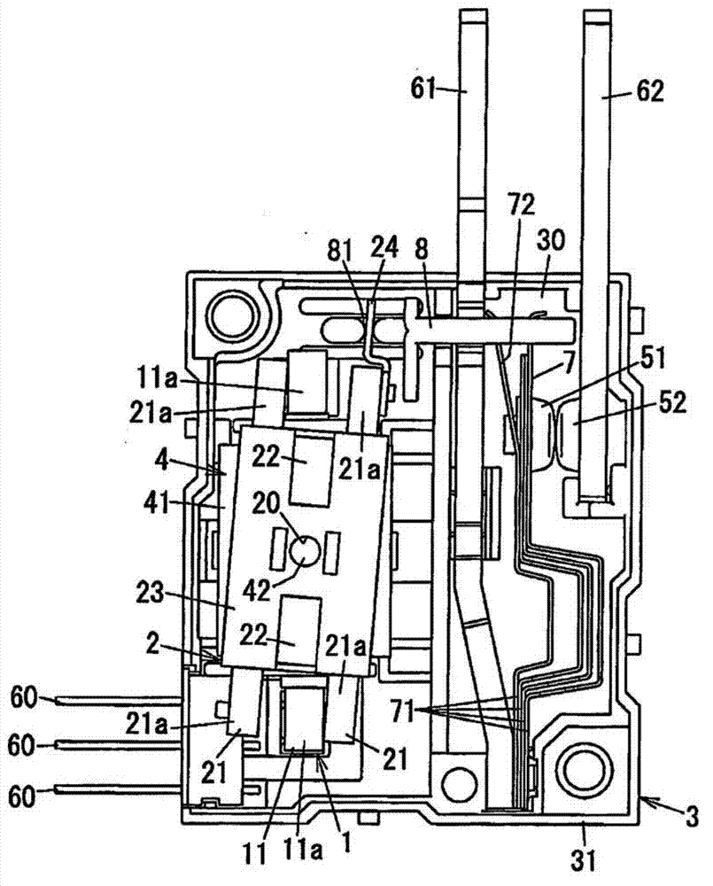
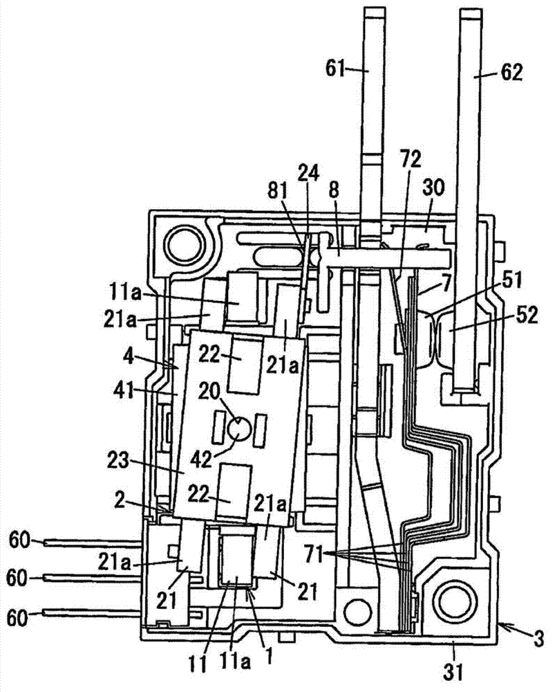
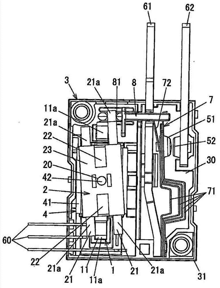
[0024] The basic structure of this embodiment is basically the same as image 3 The example shown in is the same. Common components will not be described again.

[0025] In this example, if figure 1 As shown in , the armature 2 includes a connection piece 24 connected to the right armature member 21 and protruding upward beyond the right armature member 21 . This connecting piece 24 is inserted into the armature recess 81 of the blade 8 . The connecting piece 24 is made of a plastically deformable material. The connection piece 24 is formed in a flat shape to have a thickness smaller than that of the armature member 21 . The thickness direction of the connecting piece 24 is perpendicular to the rotation axis of the armature 2 .

[0026]As for the method for joining the connecting piece 24 and the armature member 21 togethe...


PUM


Abstract

An electromagnetic relay includes an electromagnet; an armature driven by a magnetic force of the electromagnet and configured to rotate with respect to the electromagnet; a card configured to linearly move when pressed by the armature; a movable contact point moving together with the card; a fixed contact point with which the movable contact point comes into contact or out of contact in response to rotation of the armature; and a housing for storing the electromagnet, the armature, the card, the movable contact point and the fixed contact point, the electromagnet and the fixed contact point being fixed to the housing. The armature includes at least one armature member made of a magnetic material and a connector piece made of a plastically deformable material, the connector piece being arranged between the armature member and the card.

Description

technical field [0001] The invention relates to an electromagnetic relay. Background technique [0002] Conventionally, electromagnetic relays are available which bring a movable contact into contact with or out of contact with a fixed contact by rotationally driving an armature connected to the movable contact by using the magnetic force of an electromagnet (see e.g. H4 -24242 Japanese Utility Model Application Publication Document). [0003] Regarding this type of electromagnetic relay, there are known such as image 3 The electromagnetic relay shown in . [0004] will now elaborate image 3 The electromagnetic relay shown in . image 3 The electromagnetic relay shown in includes an electromagnet 1, an armature 2 rotationally driven by the magnetic force of the electromagnet 1, and a housing 3 for accommodating the electromagnet 1 and the armature 2. The electromagnet 1 is fixed to the housing 3 . In the description below, we will be based on image 3 Define top, bottom...

Claims


Application Information

Patent Timeline
IPC IPC(8): H01H50/18
CPCH01H2011/0075H01H69/01H01H51/2227H01H50/642H01H1/34H01H51/2272H01H1/48
Inventor 奥田晃弘
Owner PANASONIC INTELLECTUAL PROPERTY MANAGEMENT CO LTD
Why Eureka
Try Eureka