Conjoined frame

A frame, conjoined technology, applied in the direction of electrical components, electrical switches, coupling devices, etc., can solve the problems of weak structure, complex structure, difficult to assemble, etc., and achieve the effect of stable and reliable structure, simple structure and reduced production cost.

Inactive Publication Date: 2013-01-30
SIMON ELECTRIC CHINA
View PDF5 Cites 2 Cited by
  • Summary
  • Abstract
  • Description
  • Claims
  • Application Information

AI Technical Summary

Problems solved by technology

[0002] At present, there are many shortcomings in the socket frame on the market, such as weak structure, not durable, too complicated structure, difficult to assemble, etc.

Method used


Image

  • Conjoined frame
  • Conjoined frame
  • Conjoined frame

Examples


Embodiment Construction

[0028] In order to understand the technical content of the present invention more clearly, the following examples are given in detail.

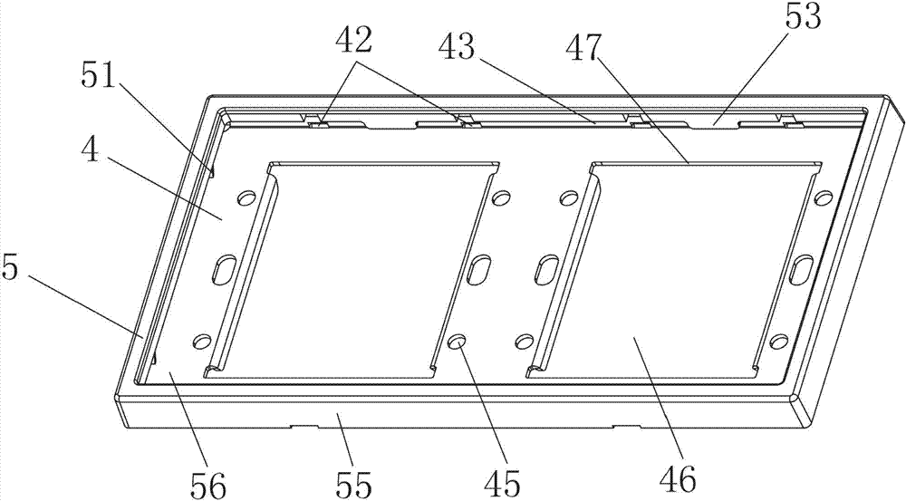
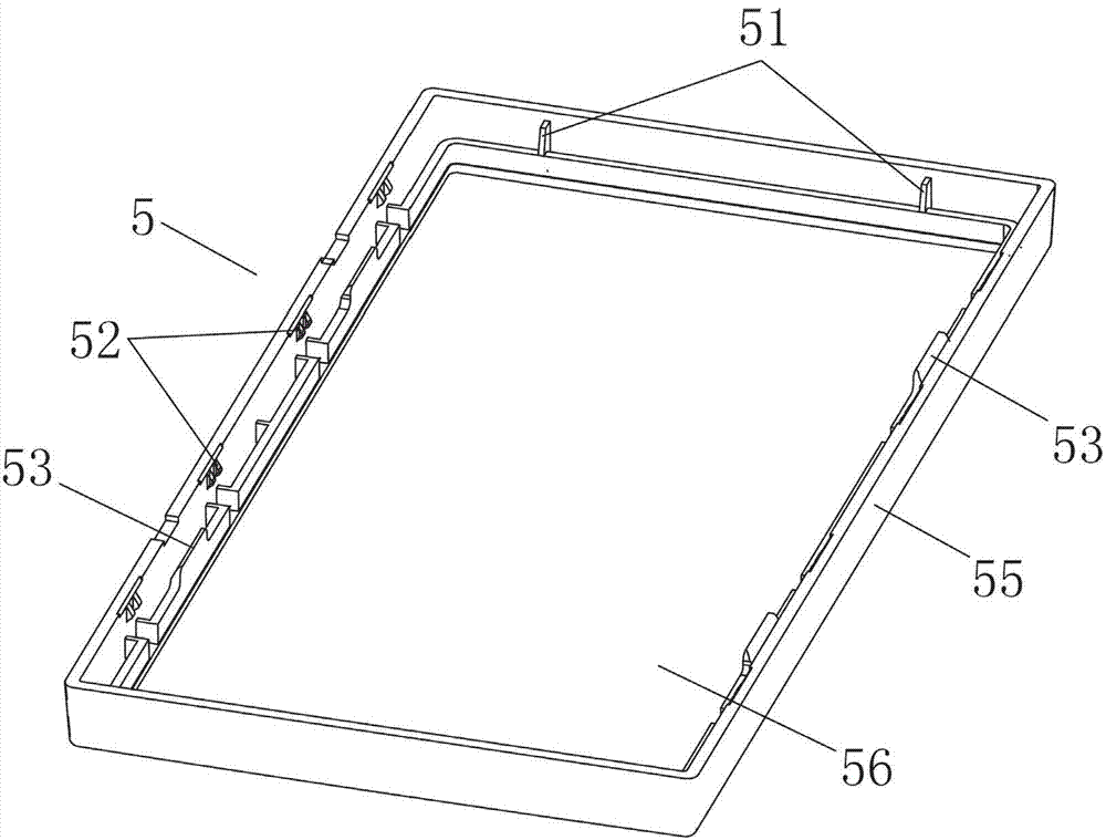
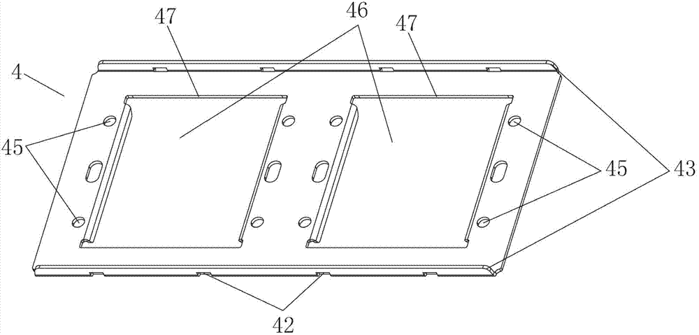
[0029] See Figure 1 ~ Figure 3 As shown, the conjoined frame of the present invention includes an outer frame 5 and an inner panel 4, the outer frame 5 has a central through hole 56 and surrounding sides 55 around the central through hole 56, and the inner panel 4 has spaced At least one through hole 46 , the inner panel 4 snaps into the peripheral side 55 , and the through hole 46 is exposed through the central through hole 56 .

[0030] Any suitable structure can be adopted for the clamping of the inner panel 4 in the surrounding side 55, please refer to Figure 1 ~ Figure 3 As shown, in a specific embodiment of the present invention, claws 52 are provided on the inner sides of the surrounding sides 55, and buckles 42 are provided on the side of the inner panel 4, and the claws 52 snap into the buckles 42. .

[0031] Or, it can also be ...


PUM


Abstract

The invention relates to a conjoined frame, which comprises an outer frame and an inner panel, wherein the outer frame is provided with a central through hole and peripheral side surfaces around the central through hole; the inner panel is provided with at least one penetrating hole which is arranged at intervals; the inner panel is in clamped connection to the peripheral side surfaces; and the penetrating holes are exposed through the central through hole. Preferably, clamping claws are arranged at the inner sides of the peripheral side surfaces, and the side surface of the inner panel is provided with fasteners which are in clamped connection with the clamping claws. Guide tongues are arranged at the inner sides of the peripheral side surfaces towards the direction of the inner panel, the side surface of the inner panel is provided with reinforcing bars which are bent to extend towards the direction of the central through hole, and the reinforcing bars are inserted between the inner sides of the peripheral side surfaces and the guide tongues and the guide tongues supports against the inner panel. The supporting ribs are arranged at the inner sides of the peripheral side surfaces and support against the inner panel. At least part of the edge of each penetrating hole is provided with a clamped connection surface. The circumference of each penetrating hole is provided with positioning holes. The conjoined frame disclosed by the invention has the advantages of smart design, concise structure, stability, firmness, reduced production cost, wide application scope and suitability for large-scale popularization and application.

Description

technical field [0001] The present invention relates to the technical field of sockets, in particular to the technical field of socket frames, in particular to a conjoined frame. Background technique [0002] At present, there are many shortcomings in the socket frame on the market, such as weak structure, not durable, too complicated structure, difficult to assemble and so on. [0003] For example, see Figure 6 ~ Figure 7 As shown, the original conjoined switch socket product has a frame 11, and the frame 11 has a spacer bar 12 for separating the functional parts 13, and also includes a decorative frame 14, and the functional parts 13 are installed in the frame 11 through the decorative frame 14. When installing Firstly, the functional parts 13 are assembled on the wall bottom box, and then the decorative frame 14 and the frame 11 are clamped and fixed to the assembled functional parts 13 from above. [0004] Therefore, it is necessary to provide a socket frame with a sta...

Claims


Application Information

Patent Timeline
Patent Type & Authority Applications(China)
IPC IPC(8): H01R13/502H01H9/02
Inventor 李永锋曹剑剑毛仲元
Owner SIMON ELECTRIC CHINA
Why Eureka
Try Eureka