
Underwater cable pulling-out mechanism

An underwater cable and cable technology, applied in circuits, electrical components, coupling devices, etc., can solve problems such as large size

Inactive Publication Date: 2014-08-06
三亚哈尔滨工程大学南海创新发展基地
View PDF8 Cites 0 Cited by
  • Summary
  • Abstract
  • Description
  • Claims
  • Application Information

AI Technical Summary

Problems solved by technology

Since the cable needs to overcome the large friction between the O-ring and the sleeve when the cable is pulled off, this device is only suitable for underwater operation equipment with heavy loads
[0004] In addition, the dumping device involving the separation of the underwater mechanical body, such as the patent document No. ZL200520097153.9, entitled "Self-rescue Release Device for Underwater Operations", uses double insurance of the motor and electric squib to achieve reliable release, but Larger

Method used


Image

  • Underwater cable pulling-out mechanism
  • Underwater cable pulling-out mechanism

Examples


Embodiment Construction

[0017] The present invention is described in more detail below in conjunction with accompanying drawing example:

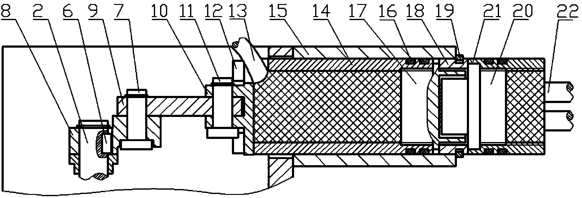
[0018] combine Figure 1~2 , the power shaft 2 is connected to the crank 8 through the key 6, the crank 8 is connected to the connecting rod 9 through the pin 7, the connecting rod 9 is connected to the socket plate 10 through the pin 11, the socket plate 10 is connected to the socket sleeve 14 through the screw 12, and the socket The sleeve 14 can slide back and forth in the cable-off sleeve 15, and a cable-off sleeve 18 is installed between the socket sleeve 14 and the plug sleeve 21, and a C-ring 19 is installed on the cable-off sleeve 18. Wherein, the cable socket 17 is connected with the socket sleeve 14 through threads, and the underwater cable 13 is vulcanized and sealed with the socket sleeve 14 after being connected with the cable socket 17. The cable plug 20 is connected with the plug sleeve 21 through threads, and the underwater cable 22 is connected wi...


PUM


Abstract

The invention aims to provide an underwater cable pulling-out mechanism which comprises a power shaft, a crank, a connecting rod, a socket plate, a socket sleeve, a cable pulling-out sleeve and a cable pulling-out shaft sleeve; the crank is connected with the connecting rod; the connecting rod is connected with the socket plate which is connected with the socket sleeve; the socket sleeve can slide in a reciprocating mode in the cable pulling-out sleeve; the cable pulling-out shaft sleeve is installed at the end part of the socket sleeve, and the cable pulling-out shaft sleeve is provided with a C-shaped ring; a plug sleeve which is used for placing the cable plug is installed beside the cable pulling-out shaft sleeve; the cable socket is installed in the socket sleeve; and the power shaft is connected with the crank. The underwater cable pulling-out mechanism does not need to overcome external water pressure; the required separating force is small; the pulling-out process has nothing to do with the gravity of abandoned equipment, and is driven by the crank; the separation is reliable; and when a plurality of cable pulling-out units are adopted, the sequential pulling-out of multiple cables can be realized.

Description

technical field [0001] The invention relates to an underwater appliance, in particular an underwater separation appliance. Background technique [0002] The ocean is rich in biological resources and mineral resources, and the development and utilization of the ocean by human beings is inseparable from underwater equipment. Due to the complex underwater operation environment, underwater equipment often faces various dangers, so it is very necessary to equip underwater equipment with a safety guarantee system. At present, the safety strategy that is often adopted is that when the underwater equipment is in danger, the secondary part of the equipment is discarded, and the important part floats out of the water relying on its own positive buoyancy. Usually, the connection between various parts of underwater equipment includes not only mechanical connections, but also electrical connections such as power cables and signal cables, such as underwater operation equipment equipped w...

Claims


Application Information

Patent Timeline
Patent Type & Authority Patents(China)
IPC IPC(8): H01R13/633
Inventor 王玉甲张铭钧殷宝吉赵文德徐建安姚峰
Owner 三亚哈尔滨工程大学南海创新发展基地
Learn More