Electric connector guide rail separation method and apparatus
A technology of electrical connectors and separation methods, which is applied to the parts of connection devices, connections, coupling devices, etc., can solve the problems of unfavorable movement of projectiles, large size space, complex synchronization, etc., and achieve small separation force and large installation space. Small size, the effect of small installation and separation space
- Summary
- Abstract
- Description
- Claims
- Application Information
AI Technical Summary
Problems solved by technology
Method used
Image
Examples
Embodiment Construction
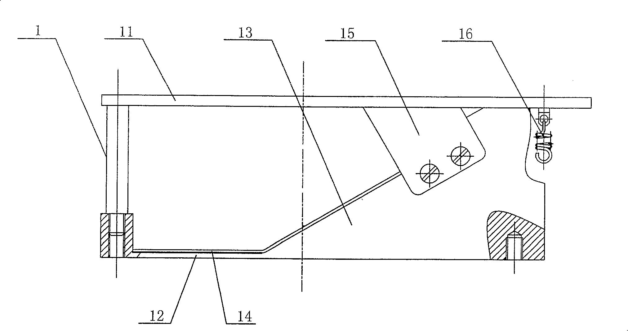
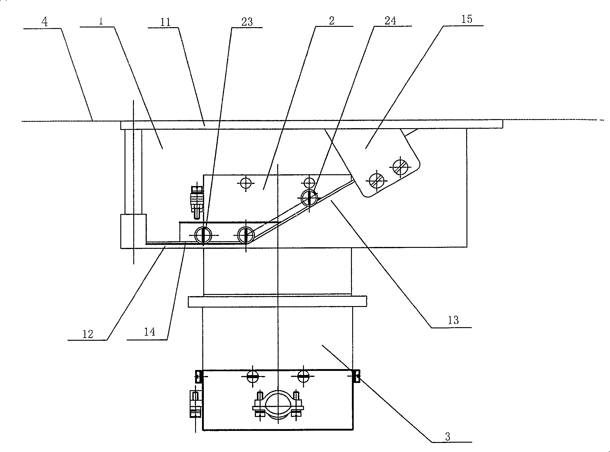
[0024] Such as figure 1 As shown, a guide rail 1 for separating electrical connectors is provided with two parallel rails, the rails are composed of a horizontal section 12 and a slope section 13, and the angle formed between the slope section 13 and the horizontal direction is preferably 30°. A slideway 14 and a baffle plate 15 are arranged on the track of the guide rail 1 . A spring 16 is provided on the guide rail 1 .
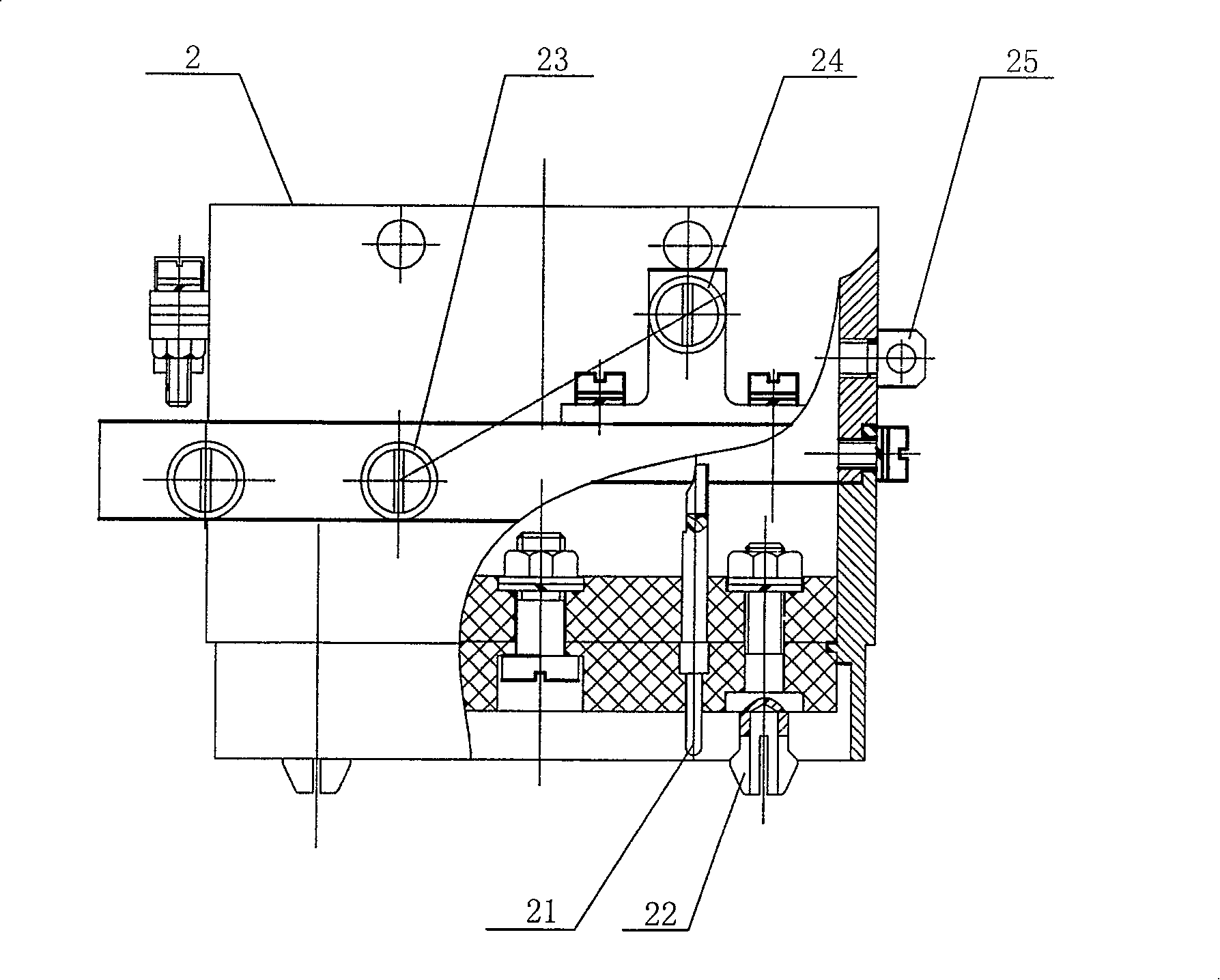
[0025] Such as figure 2 As shown, the electrical connector matching the guide rail of this structure includes a plug 2 and a socket 3. The connection and locking methods of the plug 2 and the socket 3 are: direct plug connection and spring claw locking.
[0026] The plug 2 and the socket 3 are connected by the cooperation of the spring claw guide post 22 and the post hole and the in-line pin 21 and the jack to realize the connection of the electrical connector. Two spring claw guide posts 22 are installed on the plug 2, and the socket 3 There is a step i...
PUM
 Abstract
Description
Claims
Application Information
 - R&D
- Intellectual Property
- Life Sciences
- Materials
- Tech Scout
- Unparalleled Data Quality
- Higher Quality Content
- 60% Fewer Hallucinations
Browse by: Latest US Patents, China's latest patents, Technical Efficacy Thesaurus, Application Domain, Technology Topic, Popular Technical Reports.
© 2025 PatSnap. All rights reserved.Legal|Privacy policy|Modern Slavery Act Transparency Statement|Sitemap|About US| Contact US: help@patsnap.com


