Underwater anti-short circuit separate electric connector

An electric connector and anti-short-circuit technology, which is applied in the direction of connection, components of the connection device, circuits, etc., can solve the problems of no anti-short circuit mechanism, large underwater separation force, and no water pressure balance mechanism, etc., to achieve an anti-short circuit structure Simple, reliable short-circuit proof, poor maintainability effect

Active Publication Date: 2009-06-17
杭州航天电子技术有限公司
View PDF6 Cites 0 Cited by
  • Summary
  • Abstract
  • Description
  • Claims
  • Application Information

AI Technical Summary

Problems solved by technology

[0002] Foreign underwater anti-short-circuit separation electrical connectors, such as the 8810-76H series products produced by the French SOURIAU company, have a cable-type separation method. This type of electrical connector does not have a hydraulic pressure balance mechanism, and the underwater separation force is relatively large (underwater 300m when>1700N)
Moreover, the product does not have an anti-short-circuit mechanism. After the head seat is separated, the contacts of the socket wiring part are short-circuited, so the product must be separated when the power is off.
[0003] There are domestic underwater anti-short-circuit separation electrical connectors, such as: YSF1 products, the separation method is a pull-rod mechanical separation, and the water pressure balance method is to store oil in the connection mechanism to achieve balance. The balanced water pressure effect is better, but the oil storage The operation is cumbersome, it takes several hours to store oil at a time, the efficiency is low, and the maximum separation depth can only reach 100m underwater
Although the product socket also has an anti-short-circuit structure, its structure is complex. The mating surface is sealed by potting and cannot be disassembled. Therefore, the anti-short circuit mechanism is not maintainable. Once a problem occurs, the socket must be replaced.

Method used


Image

  • Underwater anti-short circuit separate electric connector
  • Underwater anti-short circuit separate electric connector
  • Underwater anti-short circuit separate electric connector

Examples


Embodiment Construction

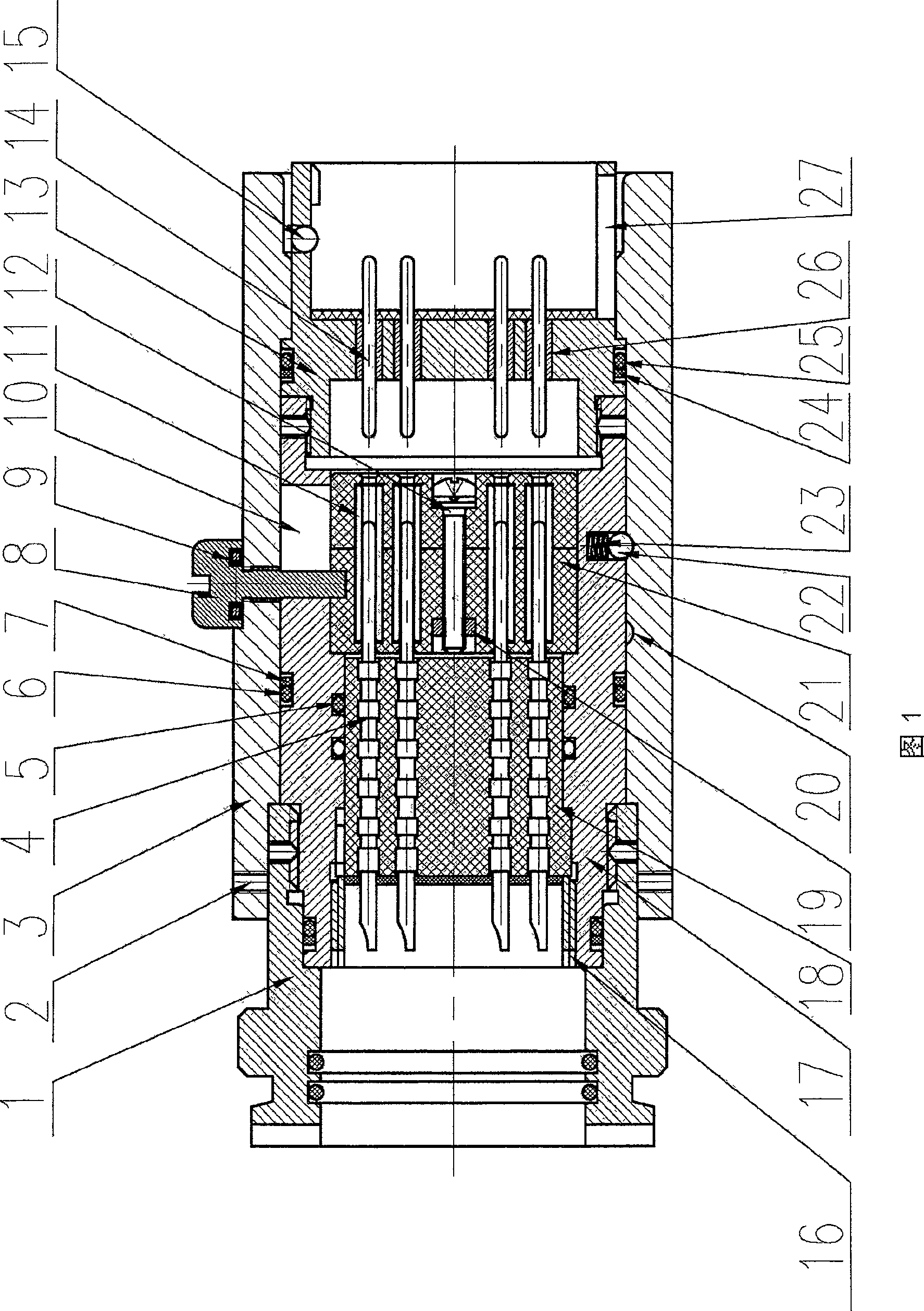
[0021] As shown in Figure 1, an unlocking sleeve 3 is arranged on the socket, and an installation hole 2 on the unlocking sleeve is connected with a release mechanism provided by the user, and the movement of the release mechanism can drive the unlocking sleeve 3 to move. The unlocking sleeve 3 is provided with a step matched with the socket housing, and the unlocking sleeve 3 can pull the socket front housing 13 and the socket rear housing 17 to move through the steps, so as to realize the complete separation of the head seat. The connecting rod 8 passes through the unlocking sleeve 3 and is connected to the socket intermediate insulator assembly 21. There are four grooves 10 on the socket rear housing 17, and the grooves 10 are arranged on the sealing assembly composed of the fourth sealing ring 6 and the first retaining ring 7 and the second sealing assembly. Between the sealing assembly formed by the six sealing rings 25 and the second retaining ring 24, there is no contact...


PUM


Abstract

The electric connector is composed of socket and plug. Wire out port of the socket is connected to back shell body of the socket, and unlocking sheath is connected to releasing gear. The unlocking sheath via sidestep pulls movement of front shell body of the socket. Connecting rod connected to insulator module in middle of socket is setup on the unlocking sheath. Through the connecting rod, the unlocking sheath drives axial motion of the insulator to turn signal inside the socket on / off. After unlocking, through water inlet troughs on plug and socket, water enters into insertion face of the connector in order to realize balance between inner and outer hydraulic pressures. The plug with two jacks is installed in insulator module. One end of the plug is always contacted to connector pins, and the other end is assorted to connector pins to implement turning electric signal on / off. With simple structure, the invented electric connector prevents short circuit reliably.

Description

technical field [0001] The invention relates to an underwater anti-short-circuit separation electrical connector, which can realize separation in deep water environment, and the socket can reliably prevent short-circuit during and after separation of products, that is, after the mating surface of the socket is short-circuited by water, the back of the socket (cable parts) contacts will not short circuit, and can be used in various underwater cable networks to play the role of electrical signal connection and separation. Background technique [0002] Foreign underwater anti-short-circuit separation electrical connectors, such as the 8810-76H series products produced by the French SOURIAU company, have a cable-type separation method. This type of electrical connector does not have a hydraulic pressure balance mechanism, and the underwater separation force is relatively large (underwater 300m when >1700N). Moreover, the product does not have an anti-short-circuit mechanism....

Claims


Application Information

Patent Timeline
Patent Type & Authority Patents(China)
IPC IPC(8): H01R13/639H01R13/523
Inventor 张利彬张俊陈佳伟
Owner 杭州航天电子技术有限公司
Why Eureka
Try Eureka