Check patentability & draft patents in minutes with Patsnap Eureka AI!

Flywheel system with a variable speed drive

A driving wheel and driver technology, applied in flywheels, transmissions, electric components, etc.

Inactive Publication Date: 2013-01-30
佛德瑞克・E・摩根 +1
View PDF3 Cites 1 Cited by
  • Summary
  • Abstract
  • Description
  • Claims
  • Application Information

AI Technical Summary

Problems solved by technology

In some cases this can be problematic, for example where the generator is an AC generator

Method used


Image

  • Flywheel system with a variable speed drive
  • Flywheel system with a variable speed drive
  • Flywheel system with a variable speed drive

Examples


Embodiment Construction

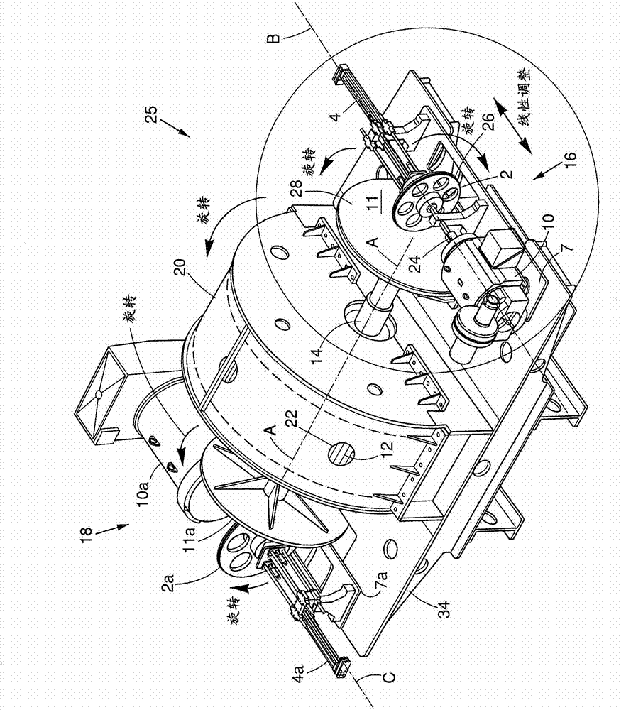
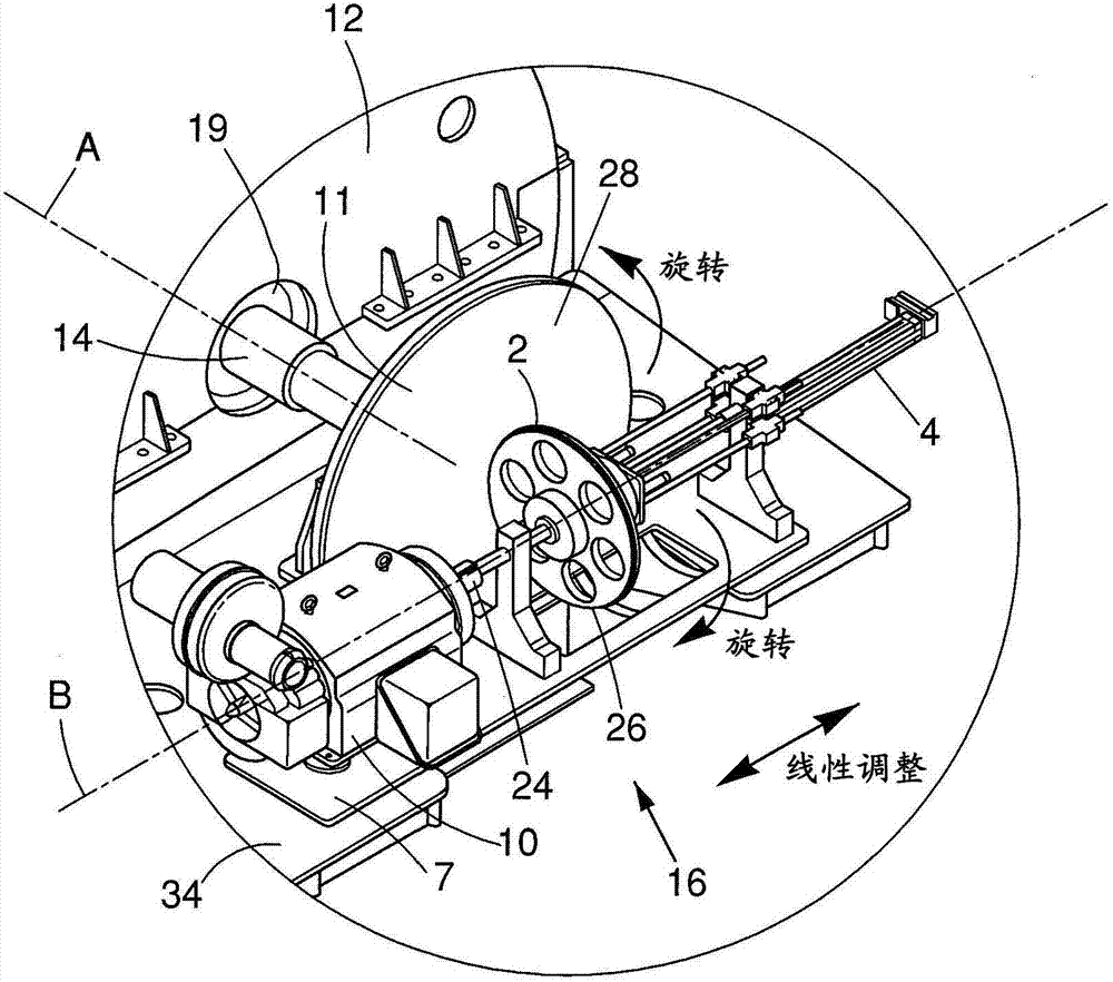
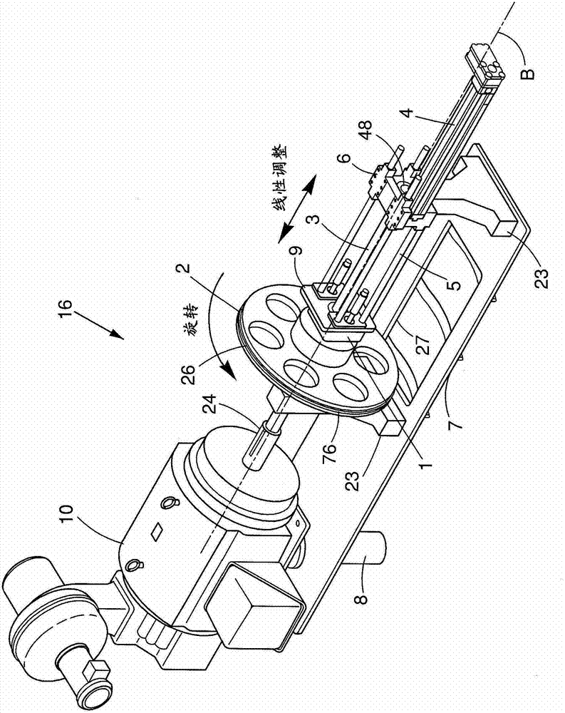
[0038] see Figures 1 to 6 , in one embodiment, the present invention may provide a flywheel system 25 having flywheel 12 rotatably coupled to motor drive assembly 16 (shown inside flywheel housing or housing 20 as seen through window 22 sections) and the generator drive assembly 18 on a support or mounting frame or bracket 34 . The environment inside the housing 20 may be in a vacuum state or have a low-density gas. The motor drive assembly 16 can bring the flywheel 12 to a desired rotational speed about the axis A, and can be adjusted to adjust the speed at which it drives the flywheel 12 . The generator drive assembly 18 can be adjusted to drive the generator 10a at a desired or constant speed, such as 1800 RPM, regardless of the speed at which the flywheel 12 is spinning. Flywheel 12 may be rotated by motor drive assembly 16 at a speed greater than 1000 RPM, for example, in some embodiments, in the range of 3000 RPM to 6000 RPM, and in some examples, up to about 10,000 R...


PUM


Abstract

A variable speed drive for a flywheel system can have a first rotatable drive plate for coupling to a rotatable flywheel. The first drive plate can be positioned about an axis of rotation and have a drive surface lying generally laterally, across or transverse to the axis of rotation. A first rotatable drive wheel can have an outer circumference for engaging and being driven by the drive surface of the first drive plate. A generator can be rotatably coupled to the first drive wheel. A first actuator can control position of the first drive wheel relative to radial drive surface location on the first drive plate for controlling drive ratio and rotational speed of the generator.

Description

[0001] This application claims priority to US Provisional Application No. 61 / 311,627, filed March 8, 2010. The entire teachings of the above applications are incorporated herein by reference. technical field [0002] none Background technique [0003] A flywheel system for generating electrical power may include a rotatable flywheel that drives a generator to generate electrical current. Over time during use, the rotational speed of the flywheel decreases. In some cases this may be problematic, for example where the generator is an AC generator. Contents of the invention [0004] The present invention can provide a flywheel system with a variable speed drive that can drive a generator at a constant rotational speed when required. [0005] In one embodiment, the variable speed drive may have a first rotatable drive plate for coupling to a rotatable flywheel. The first drive plate is positionable about an axis of rotation and has a drive surface that lies generally trans...

Claims


Application Information

Patent Timeline
Patent Type & Authority Applications(China)
IPC IPC(8): H02K7/02H02K7/116F16H15/10
CPCF16H15/10H02K7/025F16F15/30Y02E60/16H02K7/116Y10T74/19565H02K7/02
Inventor 佛德瑞克·E·摩根克里斯多夫·V·巴隆尼
Owner 佛德瑞克・E・摩根
Features
  • R&D
  • Intellectual Property
  • Life Sciences
  • Materials
  • Tech Scout
  • Unparalleled Data Quality
  • Higher Quality Content
  • 60% Fewer Hallucinations
Learn More