Electric vacuum cleaner
A vacuum cleaner and electric technology, which is applied in the direction of vacuum cleaners, suction hoses, cleaning equipment, etc., can solve the problems that the noise of electric vacuum cleaners cannot be reduced, and the noise cannot be silenced.
- Summary
- Abstract
- Description
- Claims
- Application Information
AI Technical Summary
Problems solved by technology
Method used
Image
Examples
Embodiment approach 1
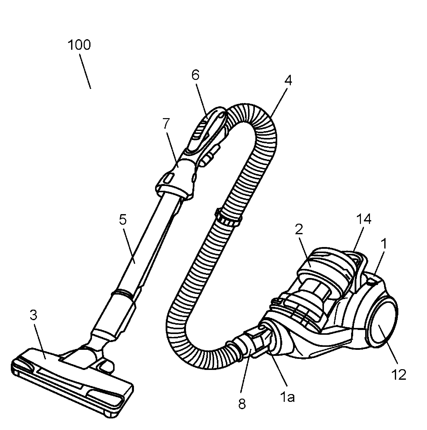
[0033] use Figure 1 to Figure 7 Embodiment 1 of the electric vacuum cleaner of this invention is demonstrated.
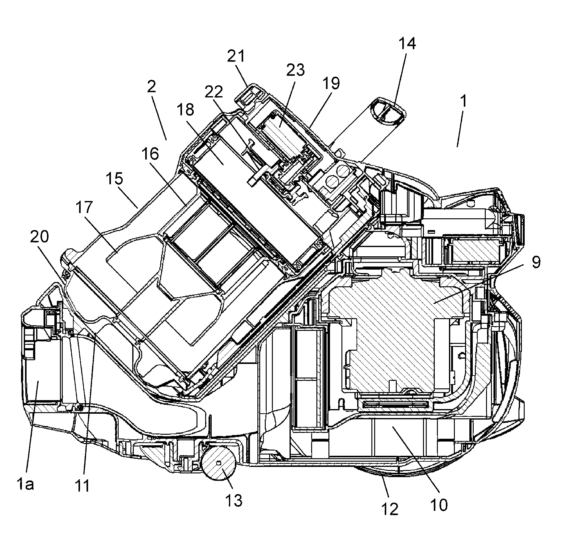
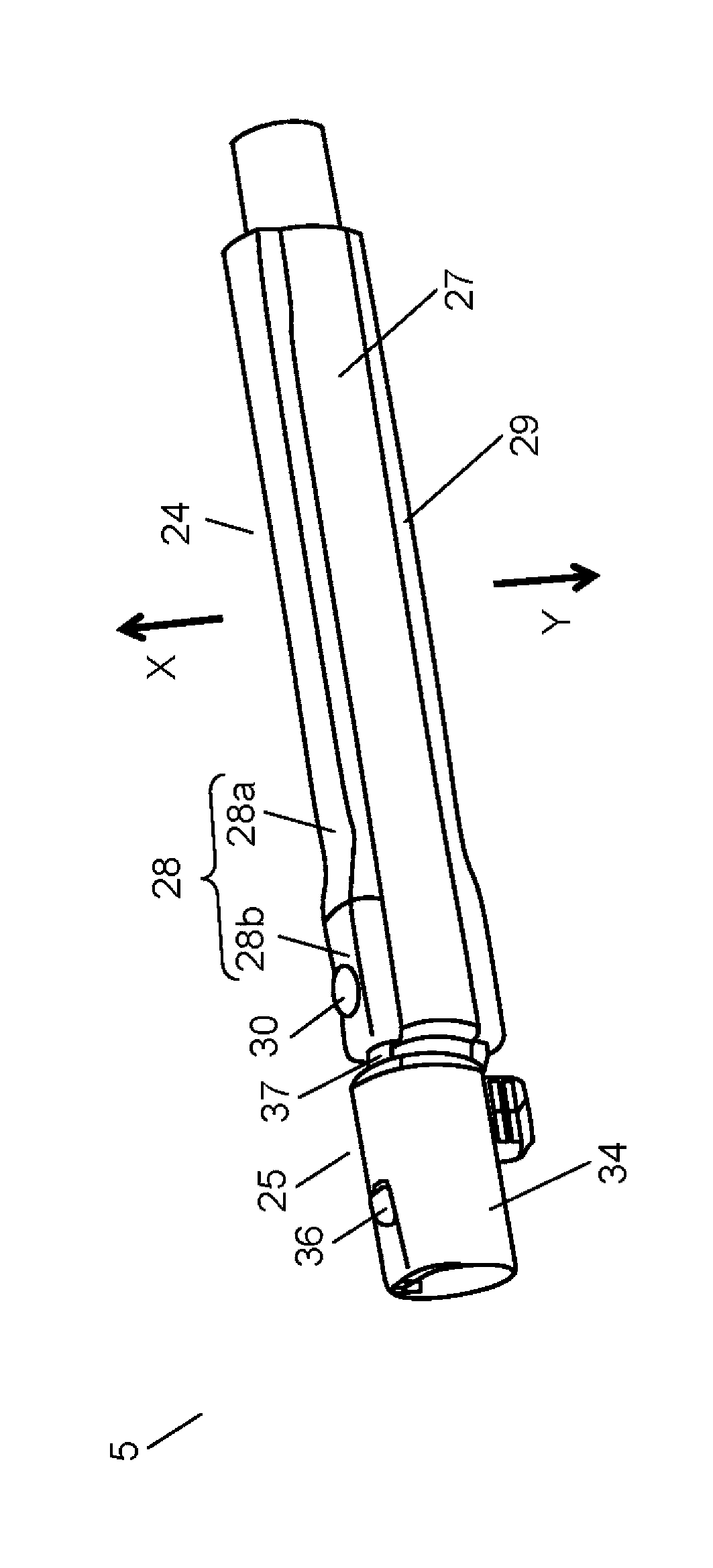
[0034] figure 1 It is an overall perspective view showing Embodiment 1 of the vacuum cleaner of the present invention. and, figure 2 It is an overall cross-sectional view of a vacuum cleaner body according to Embodiment 1 of the electric vacuum cleaner of the present invention. and, Figure 3A It is an overall perspective view of the extension pipe showing the state in which the second pipe body is housed inside the first pipe body in Embodiment 1 of the electric vacuum cleaner of the present invention, Figure 3B It is an overall perspective view of the extension pipe showing the extended state of the first pipe body and the second pipe body in Embodiment 1 of the electric vacuum cleaner of the present invention. and, Figure 4 yes Figure 3B This is an overall cross-sectional view of the extension pipe shown taken at the center in the longitudinal direct...
Embodiment approach 2
[0085] use Figure 8 Embodiment 2 of the electric vacuum cleaner of this invention is demonstrated. In addition, the same reference numerals are assigned to the same components as those in Embodiment 1, and description thereof will be omitted.
[0086] Figure 8 It is an overall cross-sectional view of the extension pipe according to Embodiment 2 of the electric vacuum cleaner of the present invention cut along the central portion in the longitudinal direction.
[0087] Such as Figure 8 As shown, in the present embodiment, the sound absorbing member 42 is composed of a first sound absorbing material 42a, a second sound absorbing material 42b, and a third sound absorbing material 42c. The first sound absorbing material 42a is arranged on the inner cover 41 side. The second sound absorbing material 42b is disposed on the side of the outer cover 35, and its density is higher than that of the first sound absorbing material 42a. The third sound absorbing material 42c is dispo...
Embodiment approach 3
[0096] use Figure 9 ~ Figure 12 Embodiment 3 of the electric vacuum cleaner of this invention is demonstrated. In addition, since the overall structure of an electric vacuum cleaner and the structure of a vacuum cleaner main body are the same as Embodiment 1, detailed description is abbreviate|omitted, and the hose which is the characteristic of this embodiment is demonstrated in detail below.
[0097] Figure 9 It is an overall perspective view of the hose in Embodiment 3 of the vacuum cleaner of the present invention. and, Figure 10 It is a central sectional view of the hose in Embodiment 3 of the vacuum cleaner of the present invention. and, Figure 11 It is an exploded perspective view of Embodiment 3 of the vacuum cleaner according to the present invention when the tip pipe is seen from above. and, Figure 12 It is an exploded perspective view of Embodiment 3 of the vacuum cleaner according to the present invention when the distal end pipe is viewed from below.
...
PUM
 Abstract
Description
Claims
Application Information
 - R&D
- Intellectual Property
- Life Sciences
- Materials
- Tech Scout
- Unparalleled Data Quality
- Higher Quality Content
- 60% Fewer Hallucinations
Browse by: Latest US Patents, China's latest patents, Technical Efficacy Thesaurus, Application Domain, Technology Topic, Popular Technical Reports.
© 2025 PatSnap. All rights reserved.Legal|Privacy policy|Modern Slavery Act Transparency Statement|Sitemap|About US| Contact US: help@patsnap.com


