Polymer electrolyte fuel cell and manufacturing method
A solid polymer, fuel cell technology, used in solid electrolyte fuel cells, fuel cells, fuel cell components and other directions, can solve the problem of difficult to form hole diameter and other issues
- Summary
- Abstract
- Description
- Claims
- Application Information
AI Technical Summary
Problems solved by technology
Method used
Image
Examples
Embodiment 1
[0046] (Preparation for forming a gas diffusion layer on the surface of the intermediate layer)
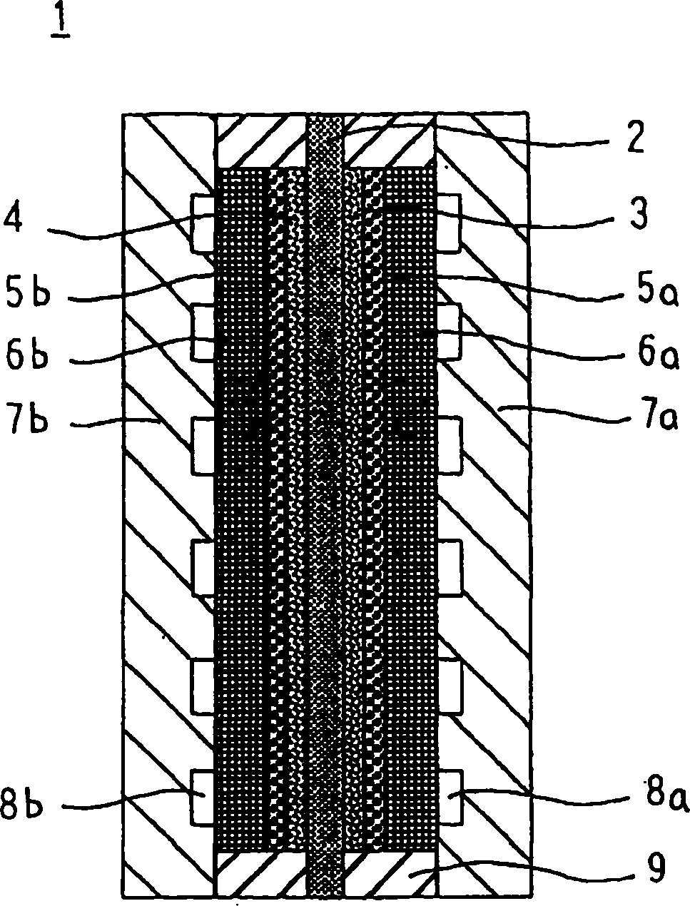
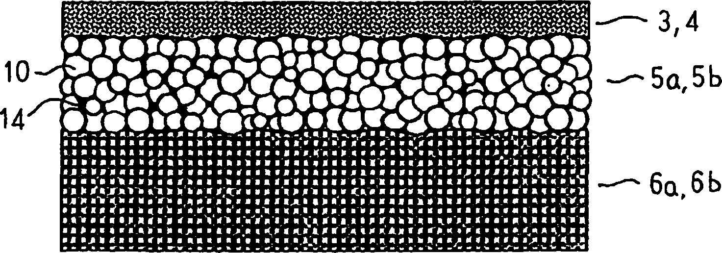
[0047]Carbon paper (manufactured by Toray: TGP-H-090) was dipped in a polytetrafluoroethylene (PTFE) aqueous dispersion (manufactured by Daikin Industries) diluted solution, dried and then heat-treated at 360°C to make it water-repellent. gas diffusion layer. Acetylene black (Denki Kagaku Kogyo Co., Ltd.: Denka Gas Black) as an electronically conductive filler with an average particle size of primary particles of about 35 nm, PTFE aqueous dispersion, nonionic dispersant, and 2 as a thickener % hydroxyethyl cellulose (HEC) aqueous solution, distilled water as a solvent mixed and dispersed slurry, add polymethyl methacrylate (PMMA) spherical particles with an average particle size of 8 μm as a heat-disappearing filler Hydration product industrial production: Techpolymer), make the solid portion ratio (the volume ratio of the PMMA particles in the slurry) reach 80%. After the slurr...
Embodiment 2
[0056] The production and operation of the battery were the same as in Example 1, except that PMMA particles with an average particle size of 8 μm were added as a heat-dissipating filler to make the solid content 50% during the production of the intermediate layer. At this time, when the air permeability of the carbon paper with the intermediate layer was measured with an air permeability meter, it was about 100 μm / (Pa·s). When a thin film consisting of only this intermediate layer is produced and the pore diameter distribution is measured, the volume ratio of pores with a pore diameter of 1 μm or more and 30 μm or less occupies about 50% of the volume of the entire intermediate layer. In addition, the solid volume ratio was 30%. Table 1 shows changes in battery voltage and battery resistance.
Embodiment 3
[0058] The production and operation of the battery were the same as in Example 1, except that PMMA particles with an average particle size of 8 μm were added as a heat-dissipating filler to make the solid content ratio 87%. At this time, when the air permeability of the carbon paper with the intermediate layer was measured with an air permeability meter, it was about 230 μm / (Pa·s). When a film consisting of only this intermediate layer was produced and the pore diameter distribution was measured, the volume ratio of pores with a pore diameter of 1 μm or more and 30 μm or less occupied about 87% of the volume of the entire intermediate layer. In addition, the solid volume ratio was 5%. Table 1 shows changes in battery voltage and battery resistance.
PUM
| Property | Measurement | Unit |
|---|---|---|
| diameter | aaaaa | aaaaa |
| thickness | aaaaa | aaaaa |
| particle size | aaaaa | aaaaa |
Abstract
Description
Claims
Application Information
 - R&D
- Intellectual Property
- Life Sciences
- Materials
- Tech Scout
- Unparalleled Data Quality
- Higher Quality Content
- 60% Fewer Hallucinations
Browse by: Latest US Patents, China's latest patents, Technical Efficacy Thesaurus, Application Domain, Technology Topic, Popular Technical Reports.
© 2025 PatSnap. All rights reserved.Legal|Privacy policy|Modern Slavery Act Transparency Statement|Sitemap|About US| Contact US: help@patsnap.com


