Cleaning machine

A cleaning machine and cleaning tank technology, applied in the field of cleaning machines, can solve the problems of water pollution, increased cost, and large water waste

Inactive Publication Date: 2013-02-06
SUZHOU DONGTAI SOLAR TECH
View PDF8 Cites 5 Cited by
  • Summary
  • Abstract
  • Description
  • Claims
  • Application Information

AI Technical Summary

Problems solved by technology

In the existing cleaning process, the water in the first few cleaning tanks is relatively dirty, and the water in the last few cleaning tanks is relatively clean, and whether it is dirty or clean water, it is directly discharged after use, and the waste of water is relatively large. Large, but also indirectly increase the cost of production

Method used


Image

  • Cleaning machine

Examples


Embodiment Construction

[0014] The present invention will be further described below in conjunction with accompanying drawing and embodiment:

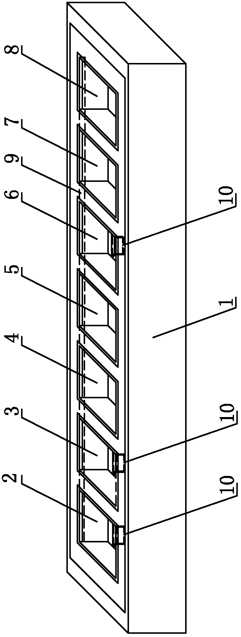
[0015] As shown in the figure, a cleaning machine includes a frame 1 and a plurality of cleaning tanks arranged on the frame 1 from the end to the end: the first cleaning tank 2, the second cleaning tank 3, the third cleaning tank 4, and the fourth cleaning tank. Slot 5, fifth cleaning tank 6, sixth cleaning tank 7 and seventh cleaning tank 8, a drainage device is arranged between at least one cleaning tank at the tail and at least one cleaning tank at the head, and the drainage device will be located at the tail cleaning tank The water is led to the cleaning tank located at the head.

[0016] In this embodiment, the drainage device includes a drainage tube 9, and the drainage tube 9 is connected between the sixth cleaning tank 7 and the seventh cleaning tank 8 at the tail and the first cleaning tank 2 and the second cleaning tank 3 at the head, And th...


PUM


Abstract

The invention relates to a cleaning machine which comprises a rack and a plurality of cleaning tanks, wherein the heads and the tails of the cleaning tanks are sequentially arranged on the rack; a drainage device is arranged between at least one cleaning tank at the tail and at least one cleaning tank at the head; and the water in the cleaning tank at the tail is drained into the cleaning tank at the head through the drainage device. In the invention, the primary cleaning water in the cleaning tank at the head is dirtier, the cleaner water in the cleaning tank at the tail is drained to the cleaning tank at the head for recycling, so that the resources are saved to a greater extent, and the production cost is lowered.

Description

technical field [0001] The invention relates to a washing machine. Background technique [0002] At present, the cut silicon wafer needs to be cleaned, and the silicon wafer must pass through at least a plurality of cleaning tanks during the cleaning process. In the existing cleaning process, the water in the first few cleaning tanks is relatively dirty, and the water in the last few cleaning tanks is relatively clean, and whether it is dirty or clean water, it is directly discharged after use, and the waste of water is relatively large. Large, but also indirectly increase the cost of production. Contents of the invention [0003] The invention provides a washing machine. [0004] In order to achieve the above object, the technical scheme adopted in the present invention is: [0005] A cleaning machine, comprising a frame, a plurality of cleaning tanks arranged on the frame head to tail in sequence, at least one cleaning tank at the tail and at least one cleaning tank a...

Claims


Application Information

Patent Timeline
Patent Type & Authority Applications(China)
IPC IPC(8): B08B3/00B08B3/10
Inventor 陈春成毛红军
Owner SUZHOU DONGTAI SOLAR TECH
Why Eureka
Try Eureka