Belt sander

An abrasive belt machine and abrasive belt technology, applied in the field of grinding devices and abrasive belt machines, can solve the problems of passing through large workpieces or special-shaped workpieces, difficult processing of large workpieces and special-shaped workpieces, etc., and achieve stable operation of the abrasive belt and convenient adjustment , The effect of fast replacement of the abrasive belt

Active Publication Date: 2013-02-06
陈渊
View PDF13 Cites 18 Cited by
  • Summary
  • Abstract
  • Description
  • Claims
  • Application Information

AI Technical Summary

Problems solved by technology

Although this belt machine is tensioned by more than three pulleys, a large area that can pass through the workpiece is formed, but in order to support and position the pulley, the frame blocks the above-mentioned area again, so ...

Method used


Image

  • Belt sander
  • Belt sander
  • Belt sander

Examples


Embodiment 1

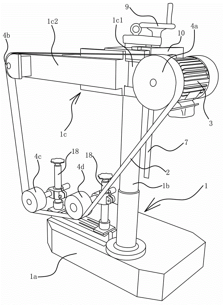
[0035] Such as figure 1 As shown, the abrasive belt machine includes a frame 1, an annular abrasive belt 2, a motor 3 and at least three pulleys 4. The pulleys 4 are all arranged inside the abrasive belt 2; the motor 3 is fixed on the frame 1; the rotating shaft of the motor 3 is connected with the pulley 4 therein. All the pulleys 4 are positioned on the frame 1 and can tension the abrasive belt 2, and the frame 1 has an escape space corresponding to the inner side of the abrasive belt 2.

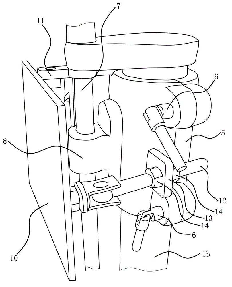
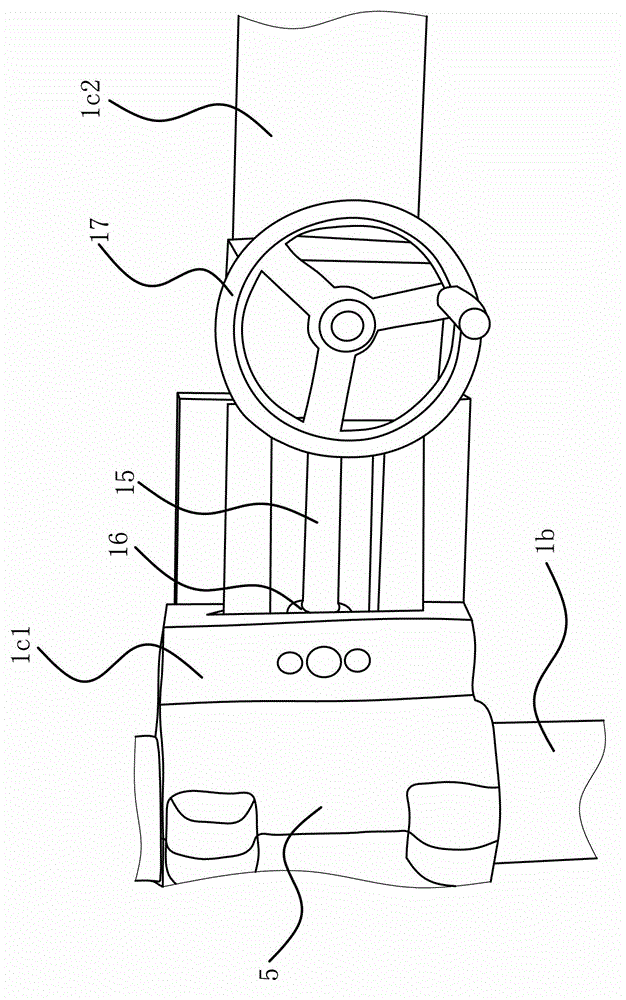
[0036] Specifically, the avoidance space is determined by the structure of rack 1; for example figure 1 As shown, the frame 1 includes a base 1a, a column 1b and a horizontal arm 1c. The lower end of the column 1b is fixedly connected to the base 1a by welding. One end of the horizontal arm 1c is fixedly connected to the upper end of the column 1b; figure 2 As shown, the column 1b is covered with a sliding sleeve 5, and the sliding sleeve 5 is provided with a locking member 6 that ena...

Embodiment 2

[0048] The structure and principle of this embodiment are basically the same as that of Embodiment 1, except that the frame 1 includes a base 1a and two uprights 1b, and the lower end of the upright 1b is fixedly connected with the base 1a; the upper end of each upright 1b is positioned with A pulley 4, at least one pulley 4 is positioned on the base 1a. There is one pulley 4 positioned on the base 1a; the above pulley 4 is located in the middle of the two columns 1b. Or the number of pulleys 4 positioned on the base 1a is two; one above-mentioned pulley 4 is located directly below the pulley 4 positioned at the upper end of a column 1b; the other above-mentioned pulley 4 is located at the upper end of another column 1b Position the pulley 4 directly below.


PUM


Abstract

The invention provides a belt sander which belongs to the technical field of operation and solves the problem that the conventional belt sander is rarely suitable for machining of large workpieces and irregular workpieces. The belt sander comprises a rack and an annular abrasive belt, wherein the inner side of the abrasive belt is provided with at least three belt wheels which are capable of tensioning the abrasive belt and are positioned on the rack; an avoiding space which corresponds to the inner side of the abrasive belt in position is formed in the rack; a motor is fixed on the rack; and a rotating shaft of the motor is connected with one belt wheel. According to the belt sander, only a grinding section of the abrasive belt penetrates through a certain space, so that the workpiece can flexibly rotate around the grinding section of the abrasive belt, and furthermore, the belt sander can be used for grinding the large workpieces and the frame-shaped, annular and other irregular workpieces. According to the belt sander, the abrasive belt can be tensioned at various structures, so that the belt sander has the advantages of being convenient to adjust, and allowing the abrasive belt to be rapidly replaced. The belt sander also can adjust the balance degree between the belt wheels, so that the belt sander has the advantage that the abrasive belt runs stably.

Description

technical field [0001] The invention belongs to the field of operation technology, and relates to a grinding device, in particular to a belt sander. Background technique [0002] The belt machine includes an abrasive belt, a motor, a frame, and a pulley or a belt roller; the abrasive belt is tensioned, and the motor drives one of the pulleys or belt rollers to move, driving the abrasive belt to move, so that the abrasive belt rubs against the workpiece, and then completes the grinding process. Cut the surface of the workpiece. Belt machines are widely used in hardware, plumbing, furniture and other industries. [0003] About the reference material of abrasive belt machine such as the polishing belt machine [application number: 200520077462. Pulleys or rollers are tensioned, and the distance between the grinding section and the non-grinding section of the abrasive belt is small, because the diameter of the pulley or belt roller used is small, so the workpiece cannot be remo...

Claims


Application Information

Patent Timeline
IPC IPC(8): B24B21/00B24B21/20B24B21/18
Inventor 陈渊
Owner 陈渊
Why Eureka
Try Eureka