Base plate and cutting method thereof

A technology for substrates and array substrates, applied in glass cutting devices, optics, glass manufacturing equipment, etc., can solve the problems of increasing the burden on staff and misjudgment of inspection machines, and achieve the effects of reducing burden, reducing misjudgment, and speeding up

Active Publication Date: 2013-02-06
SHENZHEN CHINA STAR OPTOELECTRONICS TECH CO LTD
View PDF2 Cites 14 Cited by
  • Summary
  • Abstract
  • Description
  • Claims
  • Application Information

AI Technical Summary

Problems solved by technology

[0003] However, this splitting method has the following problems:
[0006] 3. The formed slope and gap may be within the allowable accuracy, but in the actual process, it may cause misjudgment of the inspection machine and increase the burden on the staff

Method used


Image

  • Base plate and cutting method thereof
  • Base plate and cutting method thereof
  • Base plate and cutting method thereof

Examples


Embodiment Construction

[0024] The following will clearly and completely describe the technical solutions in the embodiments of the present invention with reference to the accompanying drawings in the embodiments of the present invention. Obviously, the described embodiments are only some, not all, embodiments of the present invention. Based on the embodiments of the present invention, all other embodiments obtained by persons of ordinary skill in the art without making creative efforts belong to the protection scope of the present invention.

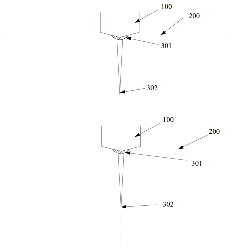
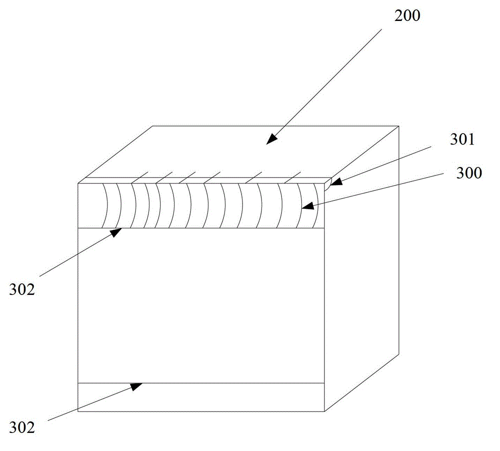
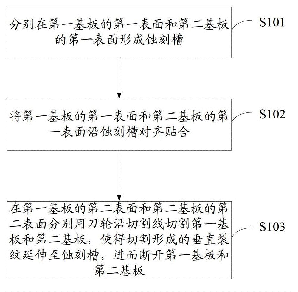
[0025] see image 3 , image 3 It is a schematic flow chart of an embodiment of the cutting method of the substrate of the present invention. The substrate includes a first substrate and a second substrate, the first substrate includes a first surface and a second surface opposite to the first surface, and the second substrate includes a first surface and a second surface opposite to the first surface. Wherein, the first substrate is a thin film transistor a...


PUM


Abstract

The embodiment of the invention discloses a cutting method of a base plate; the base plate comprises a first base plate and a second base plate; the cutting method comprises the steps of: respectively forming an etching groove on the first surface of the first base plate and the first surface of the second base plate; aligning and sticking the first surface of the first base plate and the first surface of the second base plate along the etching grooves; and respectively using a knife flywheel to cut the first base plate and the second base plate on the second surface of the first base plate and the second surface of the second base plate along cutting lines, and enabling the vertical crack formed by cutting to extend to the etching grooves to break the first base plate and the second base plate. The embodiment of the invention also discloses the base plate. In such a way, the cutting method disclosed by the invention can be used for accelerating the cutting speed of the base plate and reducing the inclination and the offset after cutting, thus reducing the erroneous judgment of a checking machine and lightening the burden of workers.

Description

technical field [0001] The invention relates to the technical field of liquid crystal panel manufacture, in particular to a substrate and a cutting method thereof. Background technique [0002] In the prior art, the cutting of liquid crystal substrates mostly adopts the method of knife wheel cutting, please refer to figure 1 and figure 2 , figure 1 It is a schematic diagram of the principle of the cutting method of the substrate in the prior art, figure 2 It is a schematic diagram of the cross-sectional structure after the substrate is cut in the prior art. The cutting method is specifically as follows: using the cutter wheel 100 to apply pressure to one side of the substrate 200, causing the surface to be damaged to form rib-shaped cracks 300, the rib-shaped cracks 300 are divided into horizontal cracks 301 and vertical cracks 302, and then the substrate 200 Pressure is applied to the surface of the other side to extend the vertical crack 302 ( figure 1 middle dotted...

Claims


Application Information

Patent Timeline
Patent Type & Authority Applications(China)
IPC IPC(8): C03B33/02G02F1/1333G02F1/1335
CPCC03B33/023B28D1/225C03B33/033G02F1/133351
Inventor 陈信华
Owner SHENZHEN CHINA STAR OPTOELECTRONICS TECH CO LTD
Why Eureka
Try Eureka