Solid electrolytic capacitor and method for manufacturing the same

Active Publication Date: 2019-11-28
MURATA MFG CO LTD
View PDF0 Cites 0 Cited by
  • Summary
  • Abstract
  • Description
  • Claims
  • Application Information

AI Technical Summary

Benefits of technology

The patent text describes a solid electrolytic capacitor that has a conductor layer made of metal foil. By using this metal foil with low surface resistance, the conductor layer can be extended to the surface of the sealing layer. This reduces the distance between the conductor layer and the outer electrode of the cathode, which helps to lower the ESR (equivalent series resistance) and ESL (equivalent series inductance) of the capacitor. Overall, this design improves the performance of the solid electrolytic capacitor.

Problems solved by technology

However, an existing structure in Patent Document 1 where a terminal extends from the capacitor element to an outer electrode in a plane direction is disadvantageous to a design for decreasing the ESR and the ESL because the distance to the outer electrode is long.
With the existing structure, it is difficult to achieve a design for increasing a ratio of the volume of the capacitance generation portion to the volume of the entire capacitor.
With the structure disclosed in Patent Document 1, it is thus difficult to design a thin solid electrolytic capacitor having a low ESR and a low ESL.
Accordingly, it is difficult to design a thin solid electrolytic capacitor having a low ESR and a low ESL.

Method used


Image

  • Solid electrolytic capacitor and method for manufacturing the same
  • Solid electrolytic capacitor and method for manufacturing the same
  • Solid electrolytic capacitor and method for manufacturing the same

Examples


first embodiment

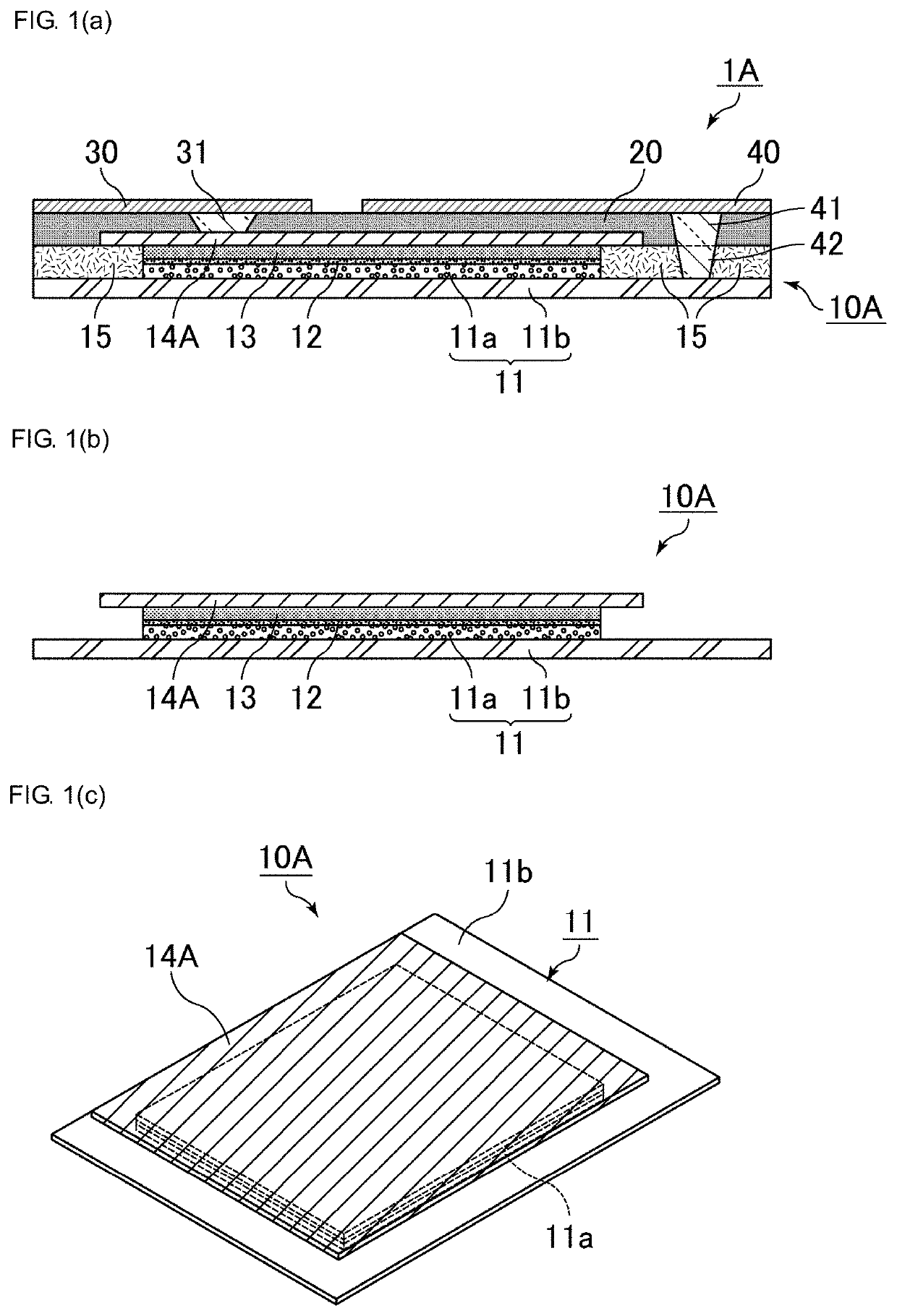
[0047]In a solid electrolytic capacitor according to the first embodiment, a sealing layer and a cathode outer electrode are disposed in this order on a conductor layer, a cathode through-electrode is disposed in the sealing layer on the conductor layer, and the conductor layer is extended to a surface of the sealing layer with the cathode through-electrode interposed therebetween. Accordingly, functions are integrated onto a surface of a valve action metal base, functional layers other than a capacitance generation portion (portion that is conducive to electrostatic capacity) are minimized, and the ratio of the volume of the capacitance generation portion to the volume of the entire capacitor can be increased. Consequently, the volumetric efficiency of the capacitance generation portion can be increased, and the solid electrolytic capacitor can be designed to be thin. For example, the thickness of the solid electrolytic capacitor is no less than 0.1 mm and no more than 0.4 mm and i...

second embodiment

[0139]According to the second embodiment, the sealing layer and the anode outer electrode are disposed in this order on the core portion, and the first anode through-electrode is disposed in the sealing layer on the core portion unlike the first embodiment. The first anode through-electrode is in direct contact with the core portion, the core portion is extended to the surface of the sealing layer with the first anode through-electrode interposed therebetween. The design of the second embodiment enables the length of the through-electrode that has a tapered conductive path to be relatively decreased because the core portion is substantially near the anode outer electrode. Consequently, the resistivity can be decreased as a whole, and a large electric current can be dealt with. In particular, when a three-terminal-structure product is used as a circuit bypass capacitor, allowable electric current capacitance between anodes is preferably set to be large. Accordingly, it is advantageou...

third embodiment

[0172]A solid electrolytic capacitor according to a third embodiment has the same structure as the solid electrolytic capacitor according to the first embodiment except that the conductor layer includes no metal foil.

[0173]FIG. 9 (a) schematically illustrates a sectional view of an example of the solid electrolytic capacitor according to the third embodiment. FIG. 9 (b) schematically illustrates a sectional view of an example of a capacitor element that is included in the solid electrolytic capacitor illustrated in FIG. 9 (a). FIG. 9 (c) schematically illustrates a perspective view of the example of the capacitor element that is included in the solid electrolytic capacitor illustrated in FIG. 9 (a).

[0174]FIG. 9 (a) is a sectional view of a solid electrolytic capacitor 100. The solid electrolytic capacitor 100 illustrated in FIG. 9 (a) includes a capacitor element 10, the sealing layer 20, the cathode outer electrode 30, and the anode outer electrode 40. As illustrated in FIG. 9 (a) ...


PUM


Abstract

A solid electrolytic capacitor is provided that includes a capacitor element having a valve action metal base with a porous portion on a first main surface of a core portion, a dielectric layer disposed on a surface of the porous portion, a solid electrolyte layer disposed on the dielectric layer, and a conductor layer disposed on the solid electrolyte layer. Moreover, the capacitor includes a sealing layer that seals a first main surface of the capacitor element, a cathode outer electrode electrically connected to the conductor layer, and an anode outer electrode electrically connected to the valve action metal base. The sealing layer and the cathode outer electrode are disposed on the conductor layer and a cathode through-electrode extends through the sealing layer on the conductor layer. The conductor layer and the cathode outer electrode are connected to each other with the cathode through-electrode interposed therebetween.

Description

CROSS REFERENCE TO RELATED APPLICATIONS[0001]The present application is a continuation of PCT / JP2018 / 003350 filed Feb. 1, 2018, which claims priority to each of Japanese Patent Application No. 2017-027980, filed Feb. 17, 2017, Japanese Patent Application No. 2017-039611, filed Mar. 2, 2017, and Japanese Patent Application No. 2017-039612, filed Mar. 2, 2017, the entire contents of each of which are incorporated herein by reference.TECHNICAL FIELD[0002]The present invention relates to a solid electrolytic capacitor and a method for manufacturing the solid electrolytic capacitor.BACKGROUND[0003]In general a solid electrolytic capacitor includes a valve action metal base including a porous layer on a surface of a base composed of a valve action metal such as aluminum, a dielectric layer that is formed on a surface of the porous layer, a solid electrolyte layer that is disposed on the dielectric layer, and a capacitor element that includes a conductor layer that is disposed on the solid...

Claims


Application Information

Patent Timeline
IPC IPC(8): H01G9/15H01G9/12H01G9/025H01G9/07H01G9/04
CPCH01G9/025H01G9/15H01G9/04H01G9/12H01G9/07H01G2009/0014H01G9/012H01G9/08H01G9/0425H01G9/10
Inventor FURUKAWA, TAKESHI
Owner MURATA MFG CO LTD
Why Eureka
Try Eureka