Pipe fitting connector

A technology of connecting parts and pipe fittings, which is applied in the direction of connecting components, rods, mechanical equipment, etc., can solve the problems of affecting pipe fittings and improving strength, and achieve the effects of convenient installation/disassembly, beautiful appearance and ingenious structural design

Inactive Publication Date: 2013-02-06
韩涛
View PDF6 Cites 5 Cited by
  • Summary
  • Abstract
  • Description
  • Claims
  • Application Information

AI Technical Summary

Problems solved by technology

This pipe connector overcomes some technical problems in the prior art to a certain extent, but still has the following defects: 1. The connector is composed of two halves, and the pipes in all directions are connected together through this connector. Connection, once the fastener bolts are loose, it will affect the pipe fittings in all directions connected by it; 2. The strength of the connection needs to be further improved

Method used


Image

  • Pipe fitting connector
  • Pipe fitting connector
  • Pipe fitting connector

Examples


Embodiment 1

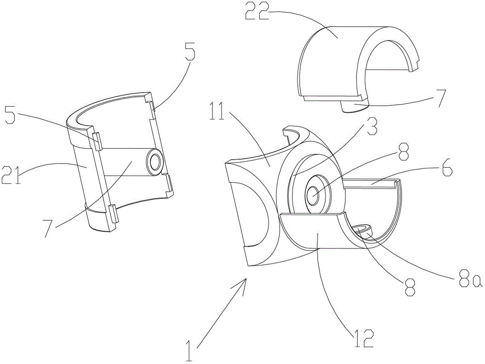
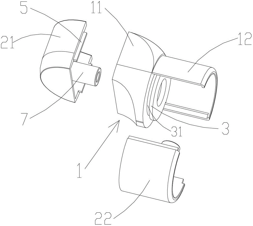
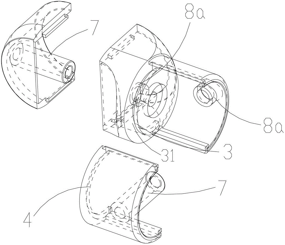
[0021] Such as Figure 1-3 As shown, the pipe connector of this embodiment includes a base 1 with two connecting parts and two housings, namely the first housing 21 and the first connecting part 11, the second housing 22 and the second connecting part 12. The second connecting part 12 is arranged on the outer surface of the first connecting part 11 and its axial direction is perpendicular to the axial direction of the first connecting part. An outwardly protruding, stepped first flange 3 is formed, and a corresponding second flange 4 is formed at the bottom of the second housing 22, and the second flange 4 can extend into the connection formed under the first flange 3 In slot 31.

[0022] The shape of the inner surface of the housing and the connecting part corresponds to the shape of the outer surface of the connected pipe fitting and can be covered on the pipe fitting. Here it is a circular arc surface, which is suitable for connecting circular pipe fittings. The connecting...

Embodiment 2

[0025] Such as Figure 4-5 As shown, the difference between this embodiment and Embodiment 1 is that the number of the housings and the connecting parts is three, namely the first housing 21 and the first connecting part 11, the second housing 22 and the connecting part 11 respectively. The second connection part 12, the third housing 23 and the third connection part 13, the second and third connection parts 12, 13 are arranged on the outer surface of the first connection part 11 and the second and third connection parts 12, 13 The axial directions are respectively perpendicular to the axial direction of the first connecting portion 11. On the outer surface of the first connecting portion 11, the joints of the second and third connecting portions are respectively formed with protruding, stepped first The protruding edge 3 forms a corresponding second protruding edge 4 at the bottom of the second and third shells 22 , 23 , and the second protruding edge 4 can extend into the co...

Embodiment 3

[0028] Such as Figure 6 As shown, the difference between this embodiment and Embodiment 1 is that the number of the housings and the connecting parts is four, respectively the first housing 21 and the first connecting part 11, the second housing 22 and the The second connection part 12, the third housing 23 and the third connection part 13, the fourth housing 24 and the fourth connection part 14, the second, third and fourth connection parts 12, 13, 14 are arranged on the first connection The outer surface of the first connecting part 11 and the axial directions of the second, third and fourth connecting parts 12, 13, 14 are respectively perpendicular to the axial direction of the first connecting part 11. On the outer surface of the first connecting part 11, the second 2. The joints of the third and fourth connecting parts form outwardly protruding, stepped first protruding edges 3 respectively, and corresponding second protruding edges 4 are formed at the bottom of the seco...


PUM


Abstract

The invention discloses a fastening piece, in particular to a pipe fitting connector used for connecting and fastening a plurality of rods or pipe fittings. The pipe fitting connector comprises a base and at least one shell, wherein the base is provided with a plurality of connecting parts with a quantity corresponding to that of shells, and the shells and the shapes of the inner surfaces of the connecting parts correspond to the shapes of the outer surfaces of connected pipe fittings and can be coated on the pipe fittings; and the inner surfaces of the shells are provided with connecting pins which are inwards extended, and the connecting parts of the base are provided with corresponding connecting holes. The pipe fitting connector has the advantages of artful structural design, stable connection, convenience in mounting / dismounting and attractive appearance.

Description

technical field [0001] The invention relates to a connecting fastener, in particular to a pipe connecting piece for connecting and fastening a plurality of rods or pipes. Background technique [0002] All kinds of furniture composed of various rods and pipe fittings can be seen everywhere, such as combined cabinets, display racks and combined sheds. This kind of furniture combined by rods or pipes has the advantages of convenient assembly and disassembly, convenient transportation and storage, and the like. In the long-term use process, people have put forward higher and higher requirements for pipe fittings: on the one hand, sufficient connection strength and stability are required to meet the long-term use requirements of various modular furniture; on the other hand, when assembled It needs to meet the requirements of quickness, convenience, simple operation and repeated disassembly. Traditional pipe fittings, such as various joints, tees, and crosses, generally use thre...

Claims


Application Information

Patent Timeline
Patent Type & Authority Applications(China)
IPC IPC(8): F16B7/08
Inventor 韩涛柴俊麟
Owner 韩涛
Why Eureka
Try Eureka