
Motor rotor structure, permanent-magnet synchronous motor and variable-frequency compressor

A permanent magnet synchronous motor and motor rotor technology, which is applied in the field of variable frequency compressors, can solve the problems of insufficient back-EMF waveform sine, affecting the performance of permanent magnet synchronous motors, and low efficiency of permanent magnet synchronous motors, so as to improve product competitiveness, The effect of optimizing the magnetic circuit and improving the performance

Active Publication Date: 2015-06-10
ZHUHAI GREE REFRIGERATION TECH CENT OF ENERGY SAVING & ENVIRONMENTAL PROTECTION
View PDF8 Cites 1 Cited by
  • Summary
  • Abstract
  • Description
  • Claims
  • Application Information

AI Technical Summary

Problems solved by technology

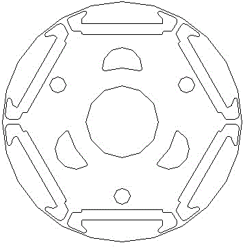
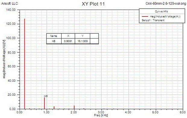
[0002] At present, the variable frequency compressor motors developed in the industry are all built-in permanent magnet synchronous motors. The rotor punching structure has a great influence on the performance of the motor and the noise of the compressor. The existing rotor structure is as follows: figure 1 As shown, the sinusoidalization of the back EMF waveform is insufficient, and the high-order harmonic content is relatively high, especially the 5th and 7th harmonics, such as figure 2 As shown in the figure, the 5th harmonic amplitude in the figure reaches 18.4V, which seriously affects the performance of the permanent magnet synchronous motor, making the efficiency of the permanent magnet synchronous motor lower and the cost increased, and the noise of the compressor using the current permanent magnet synchronous motor is relatively low. Big

Method used


Image

  • Motor rotor structure, permanent-magnet synchronous motor and variable-frequency compressor
  • Motor rotor structure, permanent-magnet synchronous motor and variable-frequency compressor
  • Motor rotor structure, permanent-magnet synchronous motor and variable-frequency compressor

Examples


Embodiment Construction

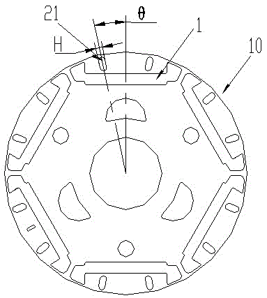
[0023] see image 3 The motor rotor structure of the present invention is a built-in permanent magnet structure, and a magnetic isolation hole 21 is provided on the outer side of the magnetic steel slot hole 1 of the rotor 10 .

[0024] The angle θ between the geometric centerline of the magnetic isolation hole and the magnetic pole centerline satisfies the relationship:

[0025] 180° / (np)-2°≤θ≤180° / (np)+2°, where n is the nth harmonic, and p is the pole logarithm.

[0026] In this embodiment, the angle θ between the geometric centerline of the magnetic isolation hole and the magnetic pole centerline is θ=180° / (np)=180° / (5*3)=12°.

[0027] The magnetic isolation holes are arranged symmetrically along the centerline of the magnetic poles. In this embodiment, there are altogether 12 magnetic isolation holes.

[0028] exist image 3 In the first embodiment shown, the magnetic isolation hole 2 is oblong, and the magnetic isolation hole has a certain width H, and the width H of...


PUM


Abstract

The invention provides a motor rotor structure which is provided with magnetic steel slots. Magnetic isolating holes are arranged on outer sides of the magnetic steel slots. A magnetic field can be affected by the magnetic isolating holes to be distributed according to a certain law, and is optimized, accordingly, high-order harmonic waves, such as fifth-order harmonic waves and seventh-order harmonic waves, are effectively reduced, and the waveform of counter electromotive force is sinusoidal effectively. The invention further provides a permanent-magnet synchronous motor and a frequency-variable compressor. A rotor of the permanent-magnet synchronous motor or the frequency-variable compressor is of the motor rotor structure. The motor rotor structure, the permanent-magnet synchronous motor and the variable-frequency compressor have the advantages that the proper magnetic isolating holes are arranged, so that the high-order harmonic waves can be effectively reduced, a magnetic circuit is optimized, the waveform of the counter electromotive force is sinusoidal effectively, the efficiency of the motor is effectively improved, and noise is effectively reduced.

Description

【Technical field】 [0001] The invention relates to the field of frequency conversion compressors, in particular to a permanent magnet synchronous motor of the frequency conversion compressor and its rotor structure. 【Background technique】 [0002] At present, the variable frequency compressor motors developed in the industry are all built-in permanent magnet synchronous motors. The rotor punching structure has a great influence on the performance of the motor and the noise of the compressor. The existing rotor structure is as follows: figure 1 As shown, the sinusoidalization of the back EMF waveform is insufficient, and the high-order harmonic content is relatively high, especially the 5th and 7th harmonics, such as figure 2 As shown in the figure, the 5th harmonic amplitude in the figure reaches 18.4V, which seriously affects the performance of the permanent magnet synchronous motor, making the efficiency of the permanent magnet synchronous motor lower and the cost increase...

Claims


Application Information

Patent Timeline
Patent Type & Authority Patents(China)
IPC IPC(8): H02K21/02H02K1/27
Inventor 钟成堡
Owner ZHUHAI GREE REFRIGERATION TECH CENT OF ENERGY SAVING & ENVIRONMENTAL PROTECTION
Learn More