Full function flocking equipment
A full-featured, hair-implanting technology, applied in the field of hair-implanting equipment, can solve the problems of easily damaged hair follicles, unsatisfactory fixation effect of implanted hair, and easy hair loss, so as to reduce the probability of damage, improve the survival rate of transplantation, and save surgery. effect of time
- Summary
- Abstract
- Description
- Claims
- Application Information
AI Technical Summary
Problems solved by technology
Method used
Image

Examples
Embodiment Construction
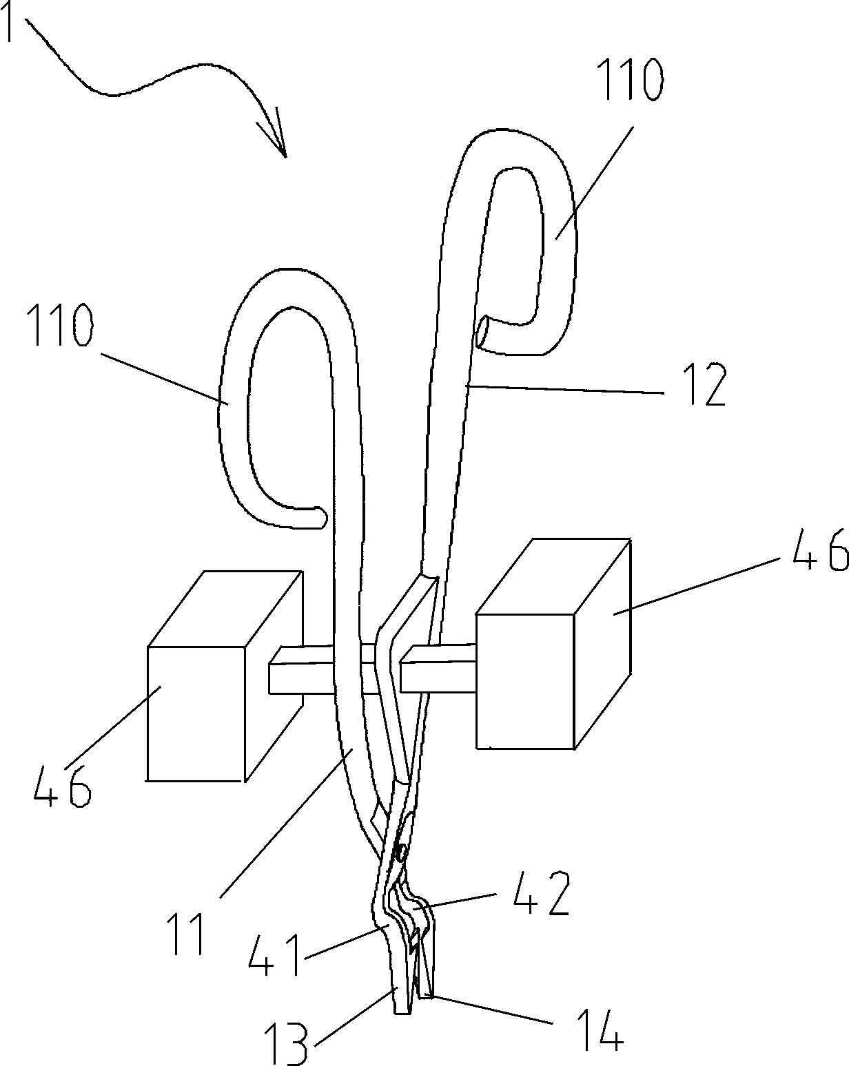
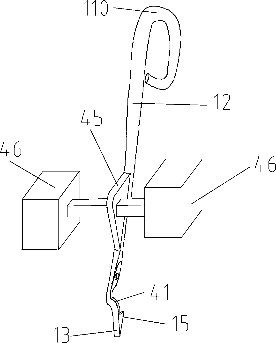
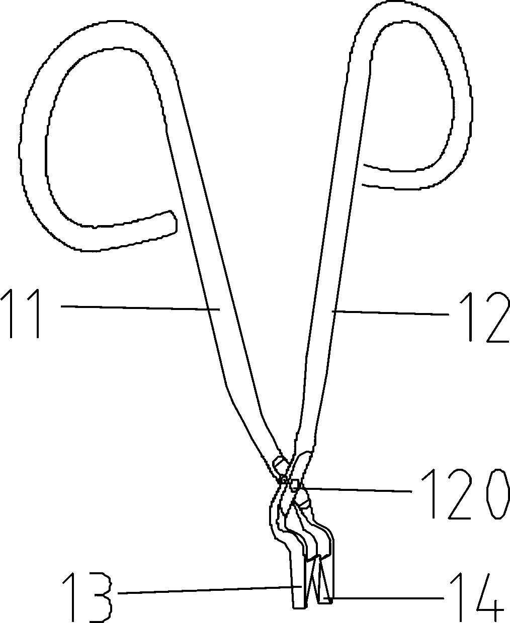
[0059] The full-featured hair-planting apparatus shown in Figure 21 includes clamp body 1 and guide support 2; Figure 1, Figure 2, Figure 3, Figure 7, shown in Figure 10, described clamp body is provided with left handle 11, right Handle 12, handle end is formed with finger ring 110; Two handles utilize rotating shaft 120 to be hinged and can open or draw close to; The handle 12 is fixedly connected as one, and the right main blade 14 is fixedly connected as one with the left handle 11.
[0060] As shown in Fig. 4, Fig. 5, Fig. 6, Fig. 7, Fig. 8, Fig. 9, Fig. 10, Fig. 11, Fig. 12, Fig. 13, Fig. 14, and Fig. 15, the left handle 11 is also fixedly provided with a limit nail 44, which The limit nail forms a limit mechanism that limits the opening angle of the two handles; the lower end of the left main blade 13 is formed with a first edge line AB extending longitudinally, and the lower end of the right main blade 14 is formed with a second edge line extending longitudinally. Edg...
PUM
 Abstract
Description
Claims
Application Information
PatSnap Eureka turns technology decisions into work you can execute. Powered by our Innovation Knowledge Graph, it runs expert workflows across engineering, life sciences, materials and intellectual property. Get your review-ready output in minutes.


