
Buffer-type artificial ankle joint

An ankle joint, artificial technology, applied in the direction of ankle joint, joint implants, joint implants, etc., can solve the problem of not being able to restore the overall motion balance of the joint and meet its biomechanical requirements, and can not ideally solve the problem of human body size. The first in the joint to undertake stress joint kinematics requirements and other issues, to achieve the effect of overcoming the overall compressive stress, wide application and alleviating stress transmission

Inactive Publication Date: 2013-02-13
黄国富 +1
View PDF5 Cites 9 Cited by
  • Summary
  • Abstract
  • Description
  • Claims
  • Application Information

AI Technical Summary

Problems solved by technology

[0002]At present, the artificial joints used in orthopedics are developing rapidly, and the purpose is to finally effectively solve the joint dysfunction of many patients, but there is no one that is more in line with the physiological anatomy and physiology of the ankle joint. functional artificial ankle joint
[0003]The prostheses used by orthopedics at home and abroad to solve ankle functional diseases are only hard bone substitutes for the distal end of the tibia and the upper end of the talus, which are not ideal To solve the kinematics requirements of the first stress-bearing joint in the large joints of the human body, it will not meet the requirements of repairing the overall motion balance of the joints and meeting its biomechanics requirements

Method used


Image

  • Buffer-type artificial ankle joint
  • Buffer-type artificial ankle joint
  • Buffer-type artificial ankle joint

Examples


Embodiment

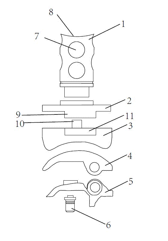
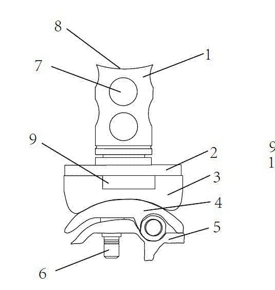
[0024] The other end of the tibial end base plate 2 is snapped together with the tibial end articular surface 3, specifically, the tibial end base plate 2 is provided with a hole for axial positioning and a flange for radial positioning 9. The articular surface of the tibial end is provided with a shaft 10 that fits into the hole and a groove 11 that fits into the flange 9 .

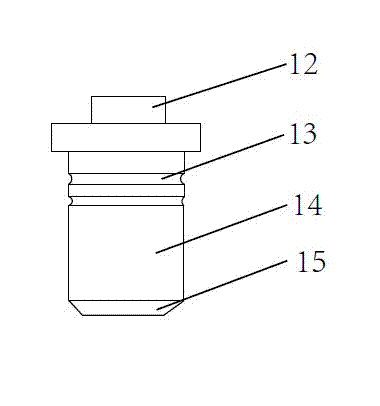
[0025] The articular surface 3 of the talar end is axially connected with the base plate 4 of the talar end, and a stop pin is provided at the joint of the shaft; the base plate 5 of the talar end is provided with a shock-absorbing hole for installing a buffer device 6 .

[0026] The implant is provided with an arc-shaped notch 8 on the edge of one end installed in the cancellous bone at the lower end of the tibia, and the resulting design of the opening 7 and the notch 8 can make the implant more conducive to bone tissue after being implanted in the cancellous bone at the lower end of the tibia. Metabol...


PUM


Abstract

The invention discloses a buffer-type artificial ankle joint which comprises an implant used for being installed in cancellous bones at the lower end of a tibia, a tibia end foundation plate, a tibia end joint surface, a talus end joint surface, a talus end foundation plate and a buffer device. The implant is hollow, and the circumferential wall is provided with holes. One end of the tibia end foundation plate is movably connected with the implant, and the other end of the tibia end foundation plate is connected to the tibia end joint surface in a clamping mode. The talus end joint surface is connected with the talus end foundation plate in a shaft matched mode. The talus end foundation plate is provided with shocking proof holes used for installation of the buffer device. The structural design of the buffer-type artificial ankle joint meets requirements of human body ankle joint anatomy, imitates ankle joint physiological movement, and fits biomechanics characteristics. The buffer device can reduce collision, reliefs stress conduction, effectively reduces movement load, and overcomes overall pressure stress. The buffer-type artificial ankle joint is simple in operation, and is wide in applicable diseases.

Description

technical field [0001] The invention relates to the technical field of artificial bone joints, in particular to a cushioning artificial ankle joint. Background technique [0002] At present, the artificial joints used in orthopedics are developing rapidly, and the purpose is to finally effectively solve the joint dysfunction of many patients. However, there is no artificial ankle joint that is more in line with the physiological anatomy and physiological functions of the ankle joint. [0003] At present, the prostheses used by orthopedics at home and abroad to solve ankle functional diseases are only hard bone substitutes for the distal end of the tibia and the upper end of the talus, which cannot ideally solve the kinematics requirements of the first stress-bearing joint in the large joints of the human body. Also just can't reach and repair the overall kinematic balance of joint and meet the requirement of its biomechanics. Contents of the invention [0004] The purpose...

Claims


Application Information

Patent Timeline
IPC IPC(8): A61F2/42A61L27/18A61L27/16
Inventor 黄国富
Owner 黄国富
Learn More