Clamping mechanism for welding machines
A clamping mechanism and welding machine technology, applied in welding equipment, auxiliary welding equipment, welding/cutting auxiliary equipment, etc., can solve problems affecting the positioning accuracy of sliding guide rails, shorten the service life of clamping mechanisms, etc., and achieve simple structure and extended The effect of service life
- Summary
- Abstract
- Description
- Claims
- Application Information
AI Technical Summary
Problems solved by technology
Method used
Image
Examples
Embodiment 1
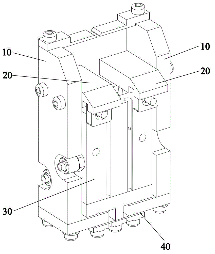
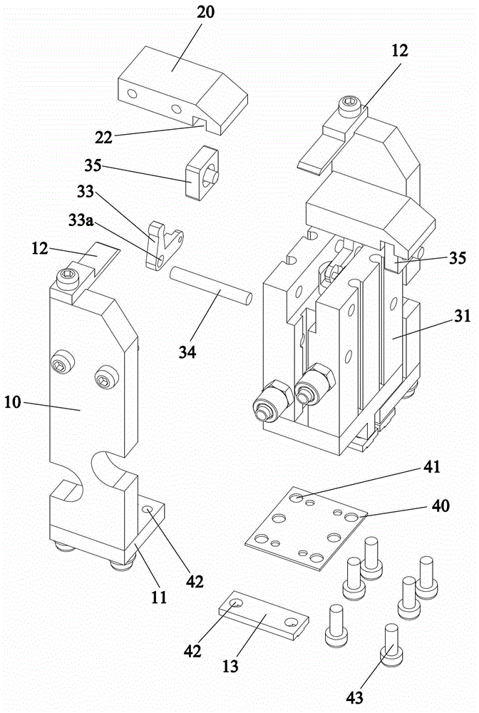
[0028] refer to Figure 1 to Figure 5 , a welding machine clamping mechanism, suitable for the clamping operation when welding the alloy cutter head on the saw blade welding machine, including a pair of symmetrically arranged cutter head clamps 10, the upper ends of the cutter head clamps 10 are respectively fixed and connected by screws There is a clamping block 20, so the clamping blocks 20 connected with the two cutter head tongs 10 are also symmetrically distributed, and the two clamping blocks 20 are respectively connected with the pneumatic fingers 30 to control the phase distance between the two clamping blocks 20. The lower ends of the two cutter head clamps 10 are respectively connected to the same flexible elastic piece 40, so that the hinge of the two cutter head clamps 10 can be realized by means of the flexibility of the elastic sheet 40, and the two clamps can be controlled by means of the pneumatic fingers 30. The distance between the blocks 20 is used to contro...
Embodiment 2
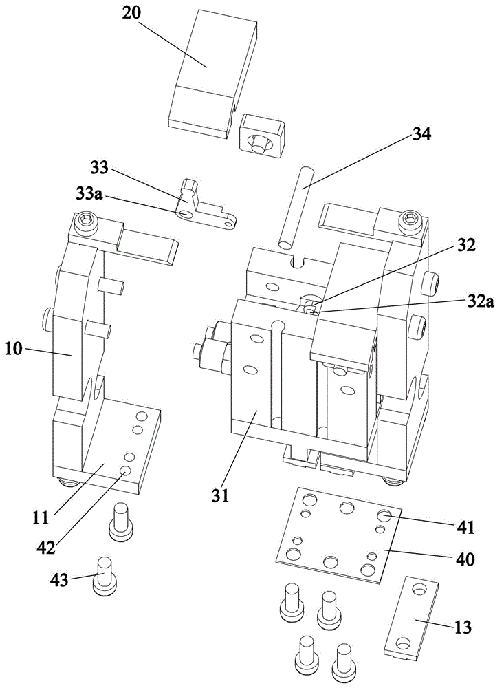
[0034] refer to Figure 6 to Figure 9 , the clamping mechanism of the welding machine in this embodiment is suitable for the clamping of the cutter head in the cutter head transmission mechanism, including two symmetrically arranged cutter head clamps 10, and the two cutter head clamps 10 are respectively connected to a pneumatic finger 30, specifically Specifically, the pneumatic finger 30 includes a body 31 and a piston rod 32, and a piston rod pin 32a is arranged at the top end 32 of the piston rod, and also includes two pins on both sides of the piston rod pin 32a that are connected through the piston rod pin 32a. Two rocker arms 33 are pivotally connected to the main body 31 through rocker arm positioning pins 34 . A fixing groove 14 is formed on the upper end of the cutter clamp 10 at a position corresponding to the end of the rocker arm 33 , and the end of the rocker arm 33 is fitted into the fixing groove 14 . Preferably, the rocker arm 33 is an L-shaped rocker arm, a...
PUM
 Abstract
Description
Claims
Application Information
 - R&D
- Intellectual Property
- Life Sciences
- Materials
- Tech Scout
- Unparalleled Data Quality
- Higher Quality Content
- 60% Fewer Hallucinations
Browse by: Latest US Patents, China's latest patents, Technical Efficacy Thesaurus, Application Domain, Technology Topic, Popular Technical Reports.
© 2025 PatSnap. All rights reserved.Legal|Privacy policy|Modern Slavery Act Transparency Statement|Sitemap|About US| Contact US: help@patsnap.com


