
Flatly-rotated car top guard
A guardrail and car top technology, which is applied in elevators, elevators in buildings, transportation and packaging, etc., can solve the problem of being unable to adapt to the small distance between the car top and the main engine, and achieve the effect of increasing the height of the guardrail and ensuring safety
- Summary
- Abstract
- Description
- Claims
- Application Information
AI Technical Summary
Problems solved by technology
Method used
Image

Examples
Embodiment Construction
[0016] The structure of the present invention will be further described below in conjunction with the accompanying drawings.
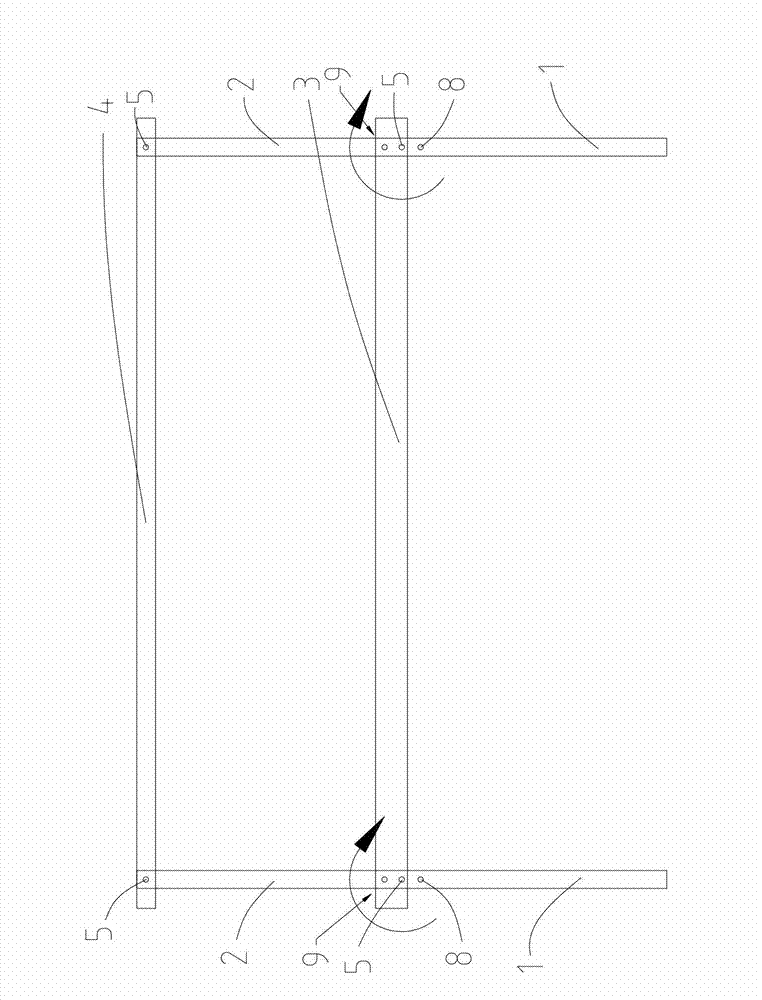
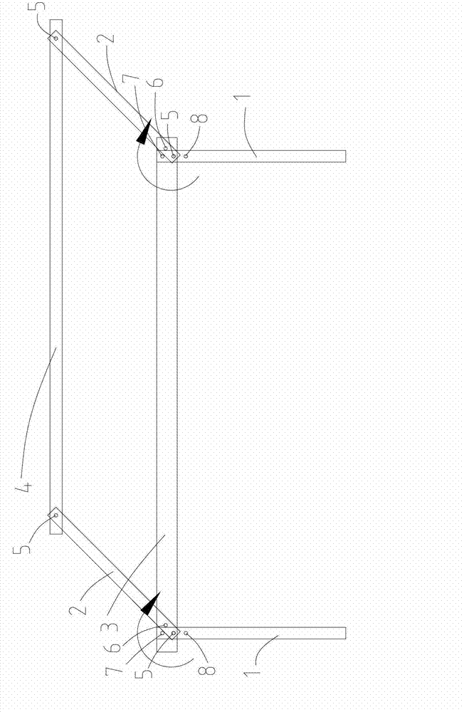
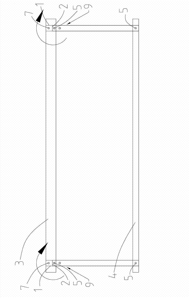
[0017] see Figure 1-3 As shown, a car top guardrail with flat rotation includes a pair of first vertical bars 1, a pair of second vertical bars 2, a first cross bar 3, a second cross bar 4, and a limit switch (not shown in the figure) , locking mechanism 9, in figure 1 Among them, a pair of first vertical rods 1 are arranged at intervals from left to right. Similarly, a pair of second vertical rods 2 are also arranged at intervals from left to right. The bottoms of a pair of first vertical rods 1 are fixed on the car roof. A first horizontal bar 3 is fixedly arranged between the tops of the bars 1, and one end corresponding to a pair of second vertical bars 2 (such as figure 1 and 2 in the lower end or as in image 3 The upper end of the middle) and the top of a pair of first vertical bars 1 or the two ends of the first cross bar 3 are rotated thr...
PUM
 Abstract
Description
Claims
Application Information