
A zero-backlash planetary transmission reduction device

A technology of reduction gear and gap planet, which is applied in the direction of transmission, transmission parts, gear transmission, etc. It can solve the problems of long processing cycle time, increased clearance between planetary gear and pin shaft, and unable to solve the problem of large backlash. , to achieve the effect of eliminating system backlash and realizing operation control

Active Publication Date: 2015-08-05
合肥波林新材料股份有限公司
View PDF7 Cites 0 Cited by
  • Summary
  • Abstract
  • Description
  • Claims
  • Application Information

AI Technical Summary

Problems solved by technology

[0004] 1. The grinding process of high-precision gears and the machining center of high-precision planetary gear carrier, the processing cycle time is long, and the cost rises sharply
[0005] 2. The meshing side clearance caused by gear wear and the increase in the matching clearance between the planetary wheel and the pin shaft cannot solve the problem of the increased backlash at all, and only scrap

Method used


Image

  • A zero-backlash planetary transmission reduction device
  • A zero-backlash planetary transmission reduction device
  • A zero-backlash planetary transmission reduction device

Examples


Embodiment Construction

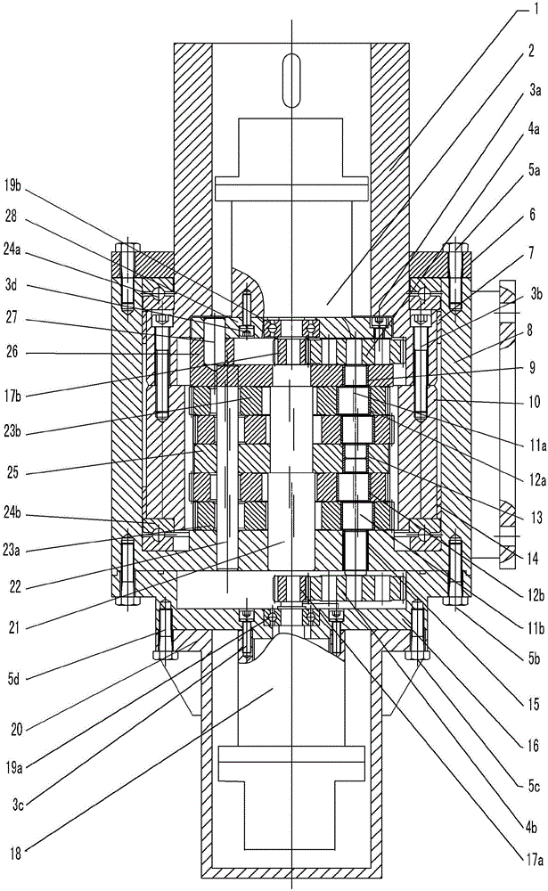
[0036] see figure 1 , This embodiment is a zero-backlash deceleration device for an automatic solar tracking system.

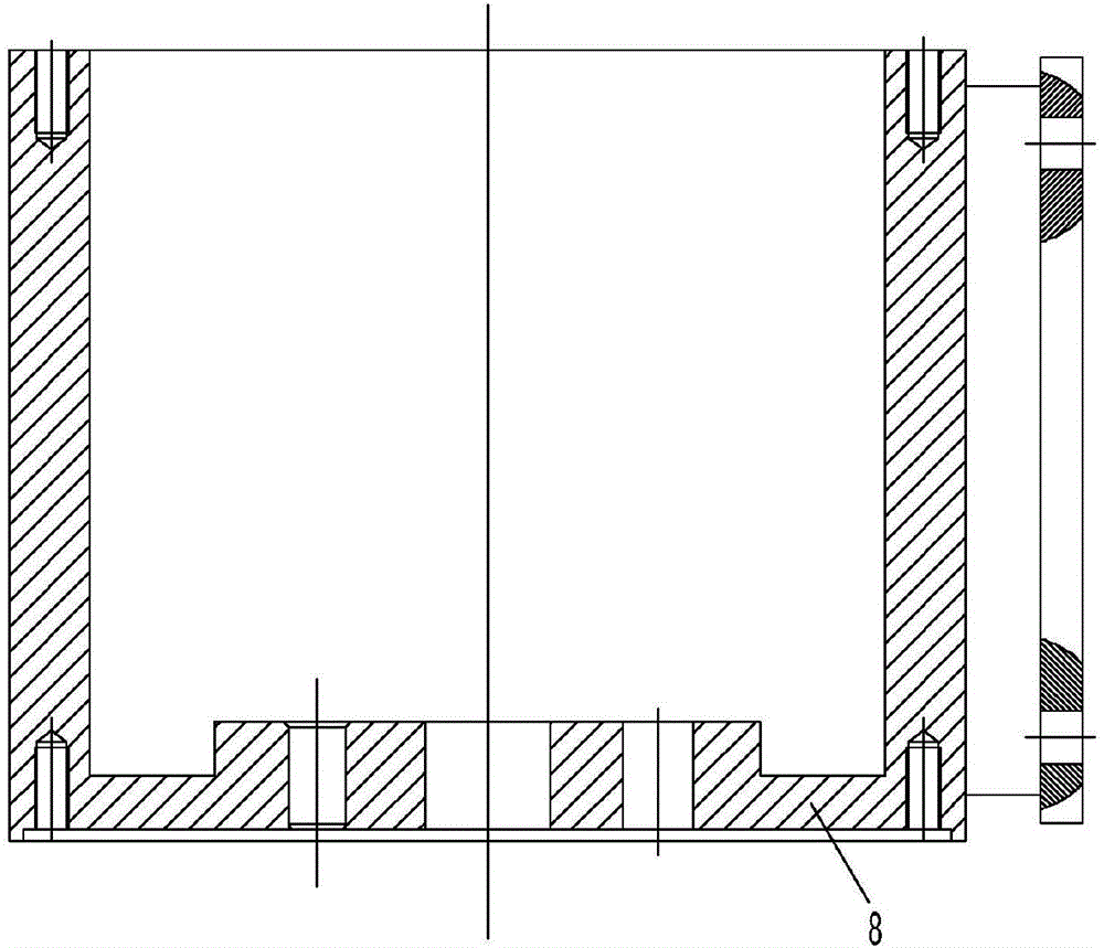
[0037] Zero-backlash planetary transmission reduction device of the present invention, output shaft 1 (see Image 6 ) is fixed on the inner ring gear 10 by the second hexagon socket head cap screw 3b, and the lower end surface of the inner ring gear 10 is provided with a lower plane bearing 24b (see Figure 15 ), the outer step end surface of the output shaft 1 is provided with an upper plane bearing 24a, and the centering bearing 7 and the ring gear centering bearing 14 are respectively installed at the upper end and the lower end of the inner hole of the ring gear seat 8; the output shaft gland 6 (see Figure 4 ) is fixed on the open end of the ring gear seat 8 by the first outer hexagonal bolt 5a; two reduction mechanisms driven by the upper motor 2 and the lower motor 18 are provided, and the upper inner rotor 23b and the lower inner rotor 23a (see Figu...


PUM


Abstract

The invention discloses a zero back clearance planetary transmission speed reducing device which is characterized in that two speed reducing mechanisms driven by two motors are arranged in one transmission device. Electric signals are utilized to control and compensate the operating mode of pulses to completely remove the meshing clearance. The two motors start and stop simultaneously and operate synchronously. Zero back clearance transmission is achieved due to the fact that no back clearance exists in clockwise or anticlockwise directions. Simultaneously, when operating parts are abraded in long-term operation and large meshing clearance occurs, electric signal control compensation pulse value is increased to completely remove the meshing clearance to achieve the zero back clearance transmission of the whole device. The zero back clearance planetary transmission speed reducing device enables one motor to be in clearance-free mesh with the clockwise direction of the device, enables the other motor to be in clearance-free mesh with the anticlockwise direction of the device, and ensures zero back clearance transmission.

Description

technical field [0001] The invention relates to planetary gear transmission in mechanical transmission, in particular to a zero-backlash planetary transmission reduction device for automatically eliminating backlash. Background technique [0002] In the planetary gear transmission, several planetary gears are usually used to transmit loads at the same time, split the power and reasonably use internal meshing, so it has a series of advantages: such as compact structure, small size, light weight, large transmission ratio range, transmission High efficiency, stable operation, low noise, and the ability to synthesize and decompose motion, etc., so it is widely used in a variety of machinery as a deceleration, speed-up and variable-speed transmission device. [0003] There is a type of planetary transmission that requires the output shaft of the planetary transmission to have two working states: counterclockwise and clockwise, and at the same time requires that the angular return...

Claims


Application Information

Patent Timeline
Patent Type & Authority Patents(China)
IPC IPC(8): F16H1/28F16H57/08F16H57/12
Inventor 孟凡纪王国良徐伟
Owner 合肥波林新材料股份有限公司
Learn More